
DMU Bogies
Introduction
There were four main types of bogies used on DMUs: Derby, Swindon, Met-Camm and B4. The principal of operation was the same for all. A centre casting was used between the vehicle and the bogie. Depending on types and usage the bogies could have a final drive, vacuum cylinder, dynamo or sanding equipment fitted.
All had an 8' 6" wheelbase. For some vehicles there were heavy duty versions of the bogies (with different rated springs), often used just at one end of a vehicle.
A common mystery about DMU bogies are "swing links", they are shown in the General Principle section below, but are often mistaken to be the Suspension Lateral Damping.
Thanks are due to David Hatt for correcting, clarifying and expanding the notes on these pages.
Types
| Type | Used on |
|---|---|
| Derby | all Derby and private contractor builds except Met-Camms |
| Met-Camm | all Met-Camm vehicles |
| Swindon | all Swindon vehicles except the Class 123s |
| B4 | Swindon Class 123s (and later one Class 120 buffet and RTC Class 129) |
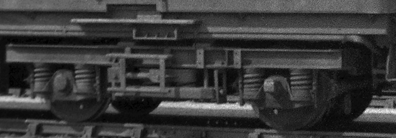
Images of the four styles in the same order:


At some point codes were introduced to differentiate the various types, using the DD series for power car bogies and DT series for unpowered vehicles. The list below is compiled from the information given on the design code diagram sheets.
Key
1 Many vehicles would have two different variations of the same type, indicated by a superscript number. For example a Class 121 power car had two DD10 bogies, one being a Mark 3 and one being a Mark 4.
| Power cars | |
|---|---|
| DD1 | |
| Mk1 | 120 batch 1/2 DMS/DMBC1, 120 DMBF, 126 |
| Mk2 | 120 batch 1/2 DMS/DMBC1 |
| DD2 | |
| Mk1 | 120 batch 32 |
| Mk2 | 120 batch 32 |
| DD3 | |
| - | 124 |
| DD4 | |
| Mk1 | 1233 |
| Mk2 | 1233 |
| DD7 | |
| Mk2 | 108 |
| Mk4 | 100 |
| DD8 | |
| Mk1 | 105 |
| DD9 | |
| Mk1 | 103 |
| Mk2 | 114 |
| DD10 | |
| Mk1 | 1164, 1225 |
| Mk2 | 1164, 1225 |
| Mk3 | 1216 |
| Mk4 | 1216 |
| Mk5 | 117/118/1197 |
| Mk6 | 117/118/1197 |
| Mk7 | 107 |
| DD13 | |
| Mk1 | 127 |
| Mk2 | 115 |
| DD14 | |
| Mk1 | 104 |
| Mk3 | 110 |
| DD15 | |
| Mk2 | 101/111 or |
| Mk3 | 101/111 |
The Class 128s were unidentified.
| Trailer cars | |
|---|---|
| DT1 | |
| Mk1 | 120 batch 1/21, 1262 |
| Mk2 | 120 batch 1/21, 1262 |
| DT3 | |
| Mk1 | 120 batch 33 |
| Mk2 | 120 batch 33 |
| DT4 | |
| Mk1 | 1244 |
| Mk2 | 1244 |
| DT8 | |
| Mk1 | 1005, 1085 |
| Mk2 | 1006 |
| Mk3 | 1086 |
| Mk6 | 1057 |
| Mk7 | 1057 |
| DT9 | |
| Mk4 | 1218 |
| Mk5 | 1218 |
| Mk6 | 117/8/99 |
| Mk7 | 117/8/99 |
| Mk10 | 115/12710 or 11 |
| Mk11 | 115/127 (non-gangwayed)10 |
| Mk12 | 115/127 (gangwayed)11 |
| Mk13 | 10712 |
| Mk14 | 10712 |
| DT9a | |
| Mk1 | 103/11413 |
| Mk2 | 103/11413 |
| DT9b | |
| Mk1 | 11614, 12215 |
| Mk2 | 11614 |
| Mk3 | 12215 |
| DT10 | |
| Mk1 | 10416 |
| Mk2 | 10416 |
| Mk3 | 11017 |
| Mk4 | 11017 |
| DT11 | |
| Mk1 | 101/111 |
| Mk4 | 101/111 |
| DT13 | |
| - | 123 |
If anyone has information on what the differences were between the variations (such as a Mark 1 and Mark 2 DD13) it would be greatly appreciated.
General Principle
The principle of operation was the same for all. In the sectioned diagram below the vehicle body (dark green) sits on the bolster (a cross-beam, shown pale green) in the centre of the bogie. The bolster sits on large coil springs (yellow) which are carried on another cross-beam (the spring plank, shown blue) which is suspended from the bogie frame (purple) by swing links (cyan). The bogie frame sits on sets of springs (yellow) that rest on top of the axle boxes (red). Thus there are two sets of springs separating the vehicle from the track.

Centre Castings
The next image shows the underside of a vehicle and where it rests on a bogie.

The main weight of the vehicle sits on the bogie bolster by way of the "centre casting", highlighted in red. The centre part is a dished shaped to allow it to self centre and to allow the bogie to rotate. The bolster has a casting in a reversed shape into which this sits (below). The "centre pin" (purple) keeps the bogie in place, it is loose and can be pushed up through the casting. When the bogie is fitted, a fastener is used in the hole at the bottom of the pin to prevent it coming loose. To prevent the body rolling excessively there are two side bearing pads (green) under the body, curved to allow for the bogie turning. There are a similar pair fitted to the top of the bogie bolster directly below them, with a small vertical clearance between.

Final Drive
Power car bogies would have a final drive mounted on the inner axle. This would be on both bogies, each connected to the nearest engine — single engined power cars would only have this on one bogie. The final drive is a gearbox that transmitted the rotational motion of the input shaft (highlighted in red) to the axle. To prevent the final drive rotating with the axle it was connected to the bogie frame by a spring (highlighted in blue) on the end of an torque 'arm'.


Vacuum Cylinder

On most power cars the bogies contained a vacuum cylinder mounted in the front. This allowed more space on the underframe for all the other equipment that was required. On unpowered vehicles, with more space available, the cylinders were often mounted on the underframe. An exception were the Wickham trailers - were there others?
The image shows a vacuum cylinder (highlighted in red) fitted in a Met-Camm power car bogie. The string (highlighted in green) was connected to the release valve, the crew would pull this to release the brakes in case the vehicle was to be towed.

In most cases a white star was painted on the underframe. This was to show where the string was, but as the string was connected to the release valve on the bottom of the brake cylinder it also indicated the location of the vacuum cylinders.
The image shows the cab end of a new GRC&W Cross-Country (Class 119) DMU, and with the star above the bogie it shows on that type the cylinder was fitted to the bogie. Some power cars, such as the Class 126s, did not have the cylinders fitted to the power car bogies.
Dynamo

On power cars the dynamo (or alternator on later vehicles) would be driven by the gearbox output or the engine itself. On unpowered vehicles the dynamo would often be mounted on the bogie frame and belt driven by the axle.
The image shows a dynamo (highlighted in green) mounted on a Met-Camm trailer car bogie. On the axle was mounted a pulley drive (highlighted in red), the large radius meant more dynamo revolutions per axle revolution.