
Vacuum Brakes
Brake Cylinder
In the early years sliding band brake cylinders were fitted to some vehicles, some had rolling ring and these became the standard. The general principle is the same for both. There were two common sizes, 18" and 21" diameter, the smaller ones were normally fitted to the 56" vehicles and the larger to the 64ft vehicles. They could be fitted in the bogies, or on the underframe.
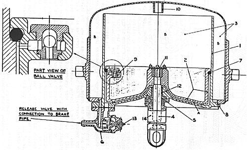
- 1 Vacuum Cylinder
- 2 Piston Head
- 3 Top Side Space
- 4 Piston Rod
- 5 Piston Rod Gland & Packing
- 6 Release Valve
- 7 Rolling Ring
- 8 Sealing Ring
- 9 Ball Valve
- 10 Stop for Piston
- 11 Piston Rod Cap
- 12 Piston Rod Guide Bush
- 13 Release Valve Lever
- 14 Piston Rod Sleeve
The diagram shows a rolling ring E1 type which became the standard on British Railways. These cylinders are of the combined type and consist of an outer steel shell which forms the top-side space and an inner cast-iron cylinder. The piston fits easily into the cylinder and has a deep head with a relieving groove to take the rolling ring in the 'brake off' position. The groove keeps the rolling ring in alignment and prevents distortion of the ring when the cylinder stands for a long time with the cylinder in the off position.
The piston carries a ball valve fitted in a cage with a direct communication between the underside of the ball and the top-side space, and with a direct passage from above the ball to the outside of the piston, and thus to the underside of the rolling ring in the off position.
The piston rod passes out of the cylinder through a gland box, which forms an air tight joint on the rod when the cylinder is under vacuum. The bottom end of the piston has a slotted hole for the pin which connects to the brake levers. The brake gear is arranged to come against a stop release, so that the piston can fall the extra distance permitted by the slot. When making a brake application the first 1/2" or so of the piston movement can thereby take place freely, which helps the piston ring to move out of its groove evenly.
When vacuum is created in the train-pipe, air passes freely from the bottom side of the piston, which will then fall by its own weight when an equal vacuum exists on both sides of it. With the piston in the 'brake off' position, air can be withdrawn from the top side through the ball valve, until a working vacuum is attained on both sides.
When the brake is applied, air enters the bottom side of the cylinder from the train-pipe and presses down on the ball valve, thereby preserving the vacuum on the top side. The piston therefore rises due to the difference in vacuum and the brakes are applied. The ring rolls between the piston and the cylinder wall, preserving an air-tight seal and also cutting off communication between the top side of the piston and the bottom side space. This prevents loss of top-side vacuum due to leakage past a worn or damaged ball valve seat.
Oversize Rolling Rings
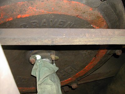
If a brake cylinder has an orange ring like this one, then it means it requires an oversize rolling ring. Stuart Mackay.
Brake Percentages
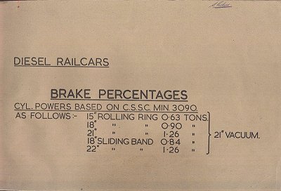
This booklet contains details of the cylinder types/sizes originally fitted to the different types, the drawings for the bogie and underframe brake details, the type of cylinder used, the brake power and brake percentage (against weight).
The full document is a 3.4Mb pdf.