Blue Square Electrical Control System
Introduction
The Blue Square control system was a development of the White Circle system introducing a new type of throttle and gear controllers and throttle motor.
Description
From the BUT 50000 Series Service Manual:
The driving controls are electo-pneumatic in operation, the air flow being regulated by a number of solenoid operated valves through switchgear housed in the driver's control table.
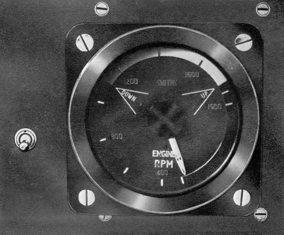
An engine speed indicator is operated by generators mounted one on each engine and indication of the speed of either engine may be obtained by movement of the indicator switch provided (pictured).
A water level switch causes the engines to be stopped when the water in the header tank reaches a low level.
Facilities for starting or stopping the engines are provided by push buttons mounted on the control panel situated in the drivers cab; auxiliary start and stop buttons are provided adjacent to each engine.
Also mounted on the control panel are the indicator lights for the oil and air pressures and "deadman's" indicator.
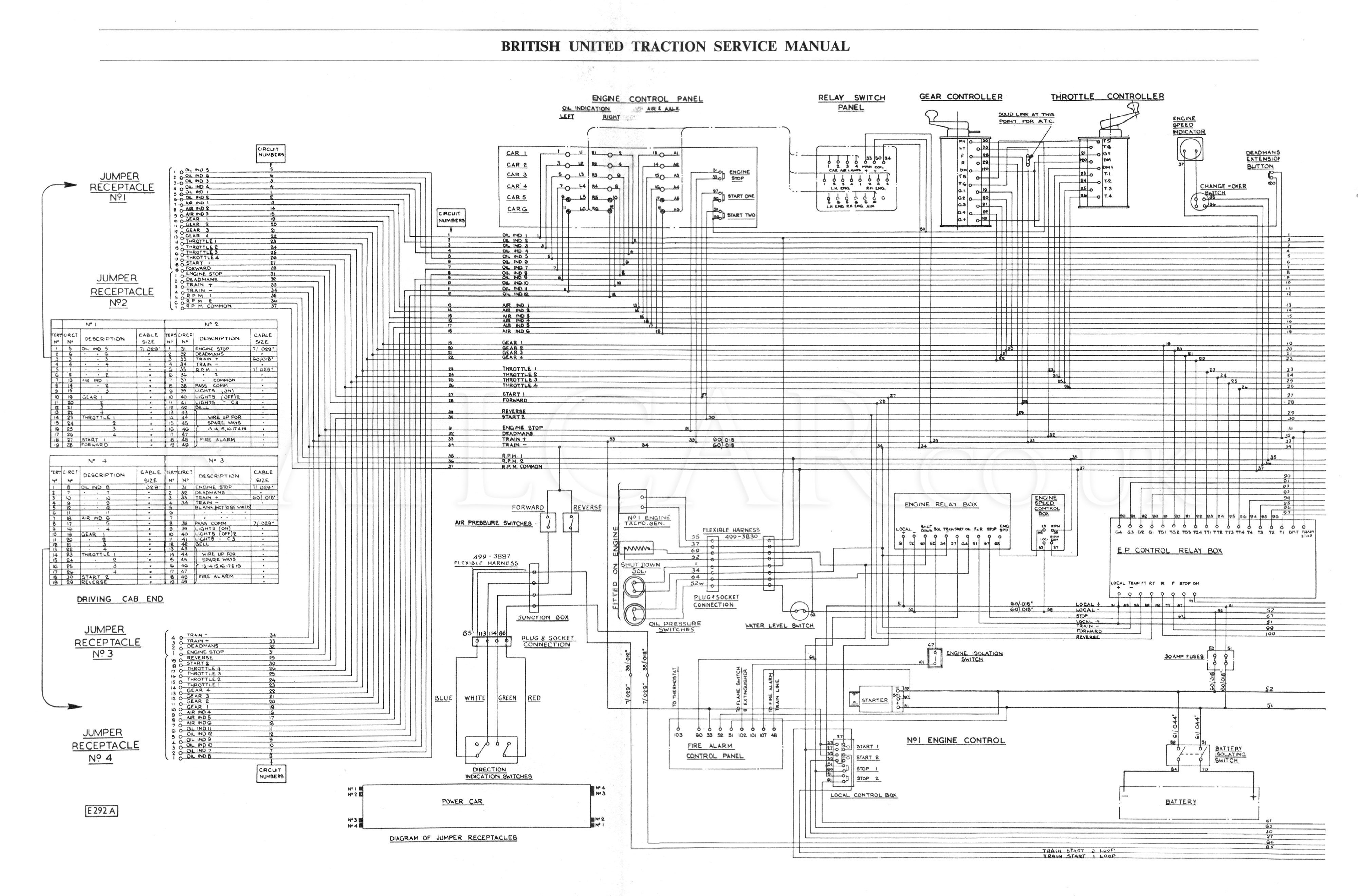
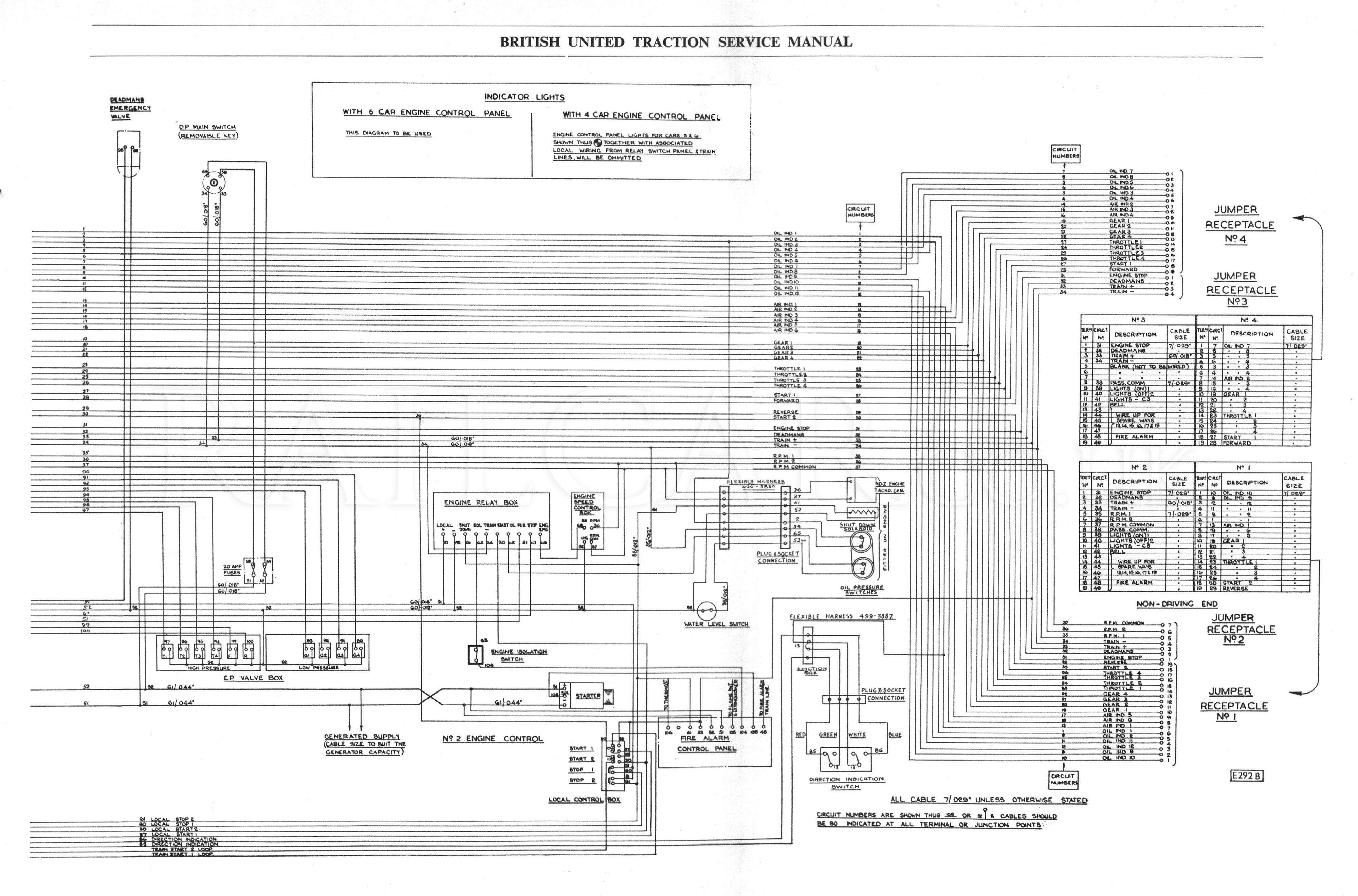
Schematic
This is the schematic wiring diagram for the Blue Square control system (two parts), taken from the BUT 50000 series service manual.
It gives a general overview of how all the items described in this section are connected.