
Gear Controller Overhaul
by John Joyce
Tools Required
2BA, 1/4" and 5/16" BSW spanners; circlip pliers; screwdrivers; small hammer; vice; adjustable spanner; toothbrush!
Materials Required
New contact pins (maybe), a little grease, washing-up liquid, time, patience, paint. Possibly circlips to suit.
Dismantling
Remove the actual handle - the dome-head nut and bolt, plus another bolt hidden under the plastic knob. Turn the whole thing upside down, and undo the four corner nuts, plus the six bolts (three pairs) holding in the 'innards'. Also undo the lock-nut and large screw - there is a ball bearing behind this to catch before it disappears onto the floor. The bottom casting should now be free, although gentle persuasion with the small adjusting tool may be required to budge it. Tap each corner in turn gently or it will jam up against the corner posts; these can be unscrewed next.
Unbolt the retainer which holds the springs which bear against the rocker arms, and retrieve these springs. They have a habit of flying off in all directions! The fixed contact assembly and terminal board can also be unbolted; retrieve the springs and washers off the two plungers on the rocker shaft. The rocker assembly is then pulled out - but don't pull too hard on the arms as they are plastic and may break. Wiggle it from side to side whilst pulling gently.
Now unbolt the clamp at the bottom of the gear cams, and the gear cam assembly will slide off (or drop off in kit form). Withdraw the gear shaft assembly from the top, retrieve the ball bearing between the gear and direction selectors, and then remove the direction cam assembly too.
I've not had any success dismantling the gear shaft from the casting it appears to be screwed into; it seems to be screwed together rather well! There is a small brass washer between the two cam assemblies, and a large brass washer above the direction one. Finally, unbolt the large brass casting to release the direction selector itself.
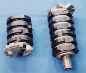
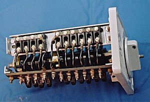
Picture 1 - gear cam assembly (on the left) and direction cam assembly (on the right). Note how these fit together - it's very easy to get them wrong!
Repair / Overhaul
The rocker assembly is perhaps the most important - at least, most troubles seem to be the rockers not moving freely. It is easily dismantled with a pair of circlip pliers, except that the brass bushes are often loose in the arms and / or rusted onto the shaft. If necessary, remove the offending arm first, and then support the brass bush in order to tap the shaft out of it. (tricky if there are several stuck - use your ingenuity!)
Clean everything up with copious quantities of washing-up liquid and toothbrush - it works surprisingly well, and doesn't seem to attack anything. The shaft itself can be de-rusted with a rotary wire brush. Make sure the rollers on each of the rocker arms do in fact roll, and if not grab them with large pliers and gently work them loose. I tried to avoid lubricating these on the basis that it will only attract dirt over the years, but gave in eventually and applied a little oil. The two plungers which provide the 'notches' usually need a little exercise to free them up too. Once dry I used a little superglue to hold the brass bushes in the rocker arms, and then reassembled it all with just a little grease in each bush. Make sure it's back together right though!
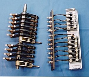
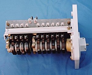
Picture 2 shows the overhauled rocker assembly and fixed contacts.
The fixed contacts can be replaced if burned - the renewable bit is just a tiny little thing, similar in shape and size to a drawing pin. If grabbed with a solid pair of pliers it can be twisted loose and pulled out; the replacement can then be pressed in with a soft-jawed vice (i.e. ordinary vice and two lengths of aluminium angle) Make sure you're not trying to pull the whole metal insert out though - only the silver tip! The moving contacts are also renewable - undo the two 4BA bolts to release it and a small spring - but I've not had chance to investigate sources for these yet.
The assorted other components benefit from stripping down, cleaning up and reassembly. With the two cam assemblies, make sure to note which cam is is which before starting - draw a picture. Picture 1 shows how they go back together; note the position of the flat on the end of the right-hand shaft. The cams themselves have a small 'pip' which (helpfully) isn't visible here; all of these should line up within each set of cams - but beware, not all seem to have these. The position of the ratchet (which gives the 'notches' for the gears or directions) is also important.
I shotblasted the various steel and aluminium bits, with the visible parts being powder-coated and the remainder treated to a few coats of spray-on silver Hammerite. I also replaced all the electrical screws and bolts - they're 2BA (see picture 2 above).
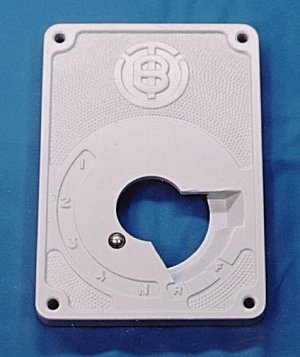
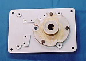
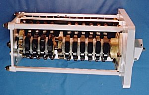
Picture 3 - the top casting cleaned and painted ready for reassembly to begin. The ball bearing interlocks gear and direction selectors.
Reassembly
First of all, clean out the threaded holes in the top casting if you've just had it painted - the small ones are 1/4" BSW and the larger four are 5/16" BSW. Now put the main direction selector body in the top casting, along with the brass bush on top (the two are probably still attached together). These are held in from below by the large brass casting.
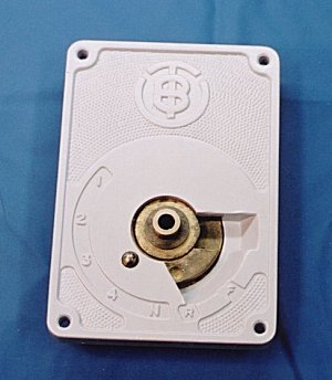
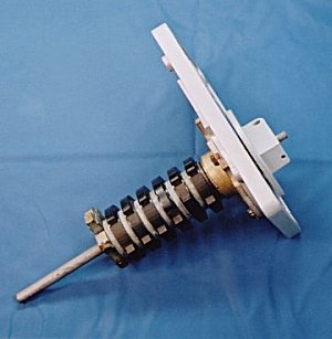
Picture 4 - Top Casting, with direction selector fitted.
Picture 5 - same, upside down.
The ball bearing can then be put in place and the gear selector and shaft lowered in. I put a little grease around this top bush.
The ball bearing serves as the interlock between gear and direction selectors: when a direction is selected, the ball can drop into the relevant hole on the direction selector, and the gear selector is released from neutral. With the gear selector in neutral, the ball can go up into the underneath of the gear selector, allowing the direction selector to move but locking the gear selector. Obviously the ball must be free to move in the top casting, which this one wasn't due to over-enthusiastic application of the powder-coating!
Next, the bank of six cams operated by the direction selector goes back. There is also the large brass washer above it. Refit this cam assembly with a little grease where it pivots on the gear selector shaft; it locates in the direction selector casting with a bit of jiggling about.
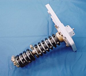
Picture 6 - direction cam assembly fitted.
The second cam assembly (for the four gears) goes in next. There is a small brass washer between the two cam assemblies; a little grease on this is suggested. Do up the clamp bolts to fasten it onto the gear selector shaft, leaving a little clearance between the two cam assemblies.
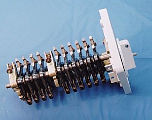
Picture 7 - now with gear selector cam assembly. From memory both selectors are in neutral in this photo.
The rocker shaft goes on next. As with removal, be gentle with it. Use a soft metal drift if you tap it in with a hammer, otherwise the bottom casting won't go on later.
Picture 8 - rocker assembly fitted. Note springs & washers on the two plungers. It's also wise to fit the three little right-angle brackets that will hold the fixed contact assembly and the spring retaining thing. [I only seem to have fitted two of them here...]
Now the fixed contact assembly. The two plungers on the rocker shaft need to have their springs and washers refitted before refitting the fixed contacts, so that they poke through the appropriate holes. Refit the spring retainer; bitter experience suggests it's easiest to leave the springs themselves out until the end - it is very easy to move the retainer slightly and fire the springs off in all directions.
Picture 9 - with fixed contact assembly fitted - make sure the two plungers go through the two matching holes in the fixed contact assembly.
Picture 10 - spring retaining thing, but no springs yet
To complete the assembly of the 'gubbins' the four corner pillars are screwed into the top casting, and the base can then be refitted. Obviously the three angle brackets holding the gubbins in need refitting too; the exact assembly order is left to the user! There is also the screw and locknut which locate the bottom of the gear shaft to refit, along with the associated ball bearing; screw the screw in until until the ball bearing just centres the gear shaft, and then tighten the locknut.
Picture 11 - base attached at the 4 corners and bolted to the three right-angle brackets.
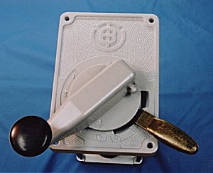
Finally, attach the handle and Bob's your Uncle, allegedly.
Picture 12 - the finished item. I suppose some smartarse will want a polished brass 'spoon' to go with it now!
Testing
Not a lot to it, really; make sure it works! Insert the direction 'spoon' and ensure contacts operate correctly: from the top, 1,4,5,6 are closed in both directions, 2 in forward, and 3 in reverse. They should close as the roller on the ratchet drops into its notch, and then remain closed even if the spoon is moved a little. Make sure the spoon moves easily without the gear selector trying to move as well. Similarly, the relevant gear contacts should close positively as the roller drops into a notch on the other ratchet, and not reopen if the gear selector is gently moved.
I do find that the controllers 'feeling' right is essential to enjoyable driving. Some are very vague and hard to tell when in gear; others need a crowbar to change gear or a bit of juggling to change direction. If everything has been cleaned up and assembled correctly, the degree of 'notchiness' should turn out right. If it's too slack, it may be that the ratchet springs have gone soft, and can be packed out with a washer; if too stiff, check the assembly (and also 'other bits' below for a possible remedy), and apply a little grease to the surface of the brass ratchet cam. I've not had any joy getting the rollers to roll correctly on these as they always seem to have substantial 'flats'!
Other bits
Both of the two gear controllers I have 'done' completely refused to work on reassembly; trying to change gear resulted in the direction selector trying to move too, and then the interlock stopping both from moving - not very helpful. Everything was binding up and generally not playing 'ball'. Increasing the distance between the two sets of cams, and playing with the screw and ball bearing at the bottom, helped a little, but not enough. Several attempts at dismantling and reassembly (and chipping Evan's powder-coated top - oops) got me nowhere. In the end I made up a thin brass washer which goes on the the gear selector shaft, before refitting it through the direction selector, and all was well. It's something like 1/2" inside dia, 7/8" outside dia. The two throttle controllers have needed similar treatment too for exactly the same trouble; the DSD wouldn't return when reliably when released.
The three small angle brackets that hold the innards to the top casting may be best left 'in situ'; at the other end I unbolted them from the bottom casting. It depends exactly what tools are available (ie open-end / ring spanners or socket set). And don't forget to bend up all those lock tabs!