
DMU Engines
1950s Overhauls
Adapted from an article that appeared in the 11/9/59 issue of Railway Gazette magazine, all photographs by British Railways.
With all the DMUs being or due to be introduced throughout the country, the LMR allocated an area in Derby works to deal with the repair and overhaul of the engines. Good forward planning saw a workshop in which tender tanks had been repaired, emptied, and completely reconditioned early in 1955. By the allocation of a separate shop, the area was properly arranged in sections with complete separation of dismantling and assembly, personnel and components. This allowed the work to be done more efficiently than if they were handled in the already established diesel erecting shop. The shop was reconditioned and started work at the end of 1955.
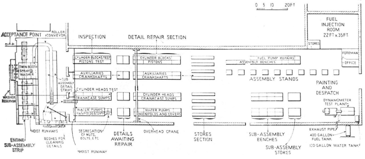
Batches of dismantled components found fit for further use were sent to a central store, and not direct back to the same engine from which they were taken. At the entrance end of the shop was a 30ft x 47ft annexe in which the engines were cleaned externally, stripped, and then all components cleaned. Thor Pneumatic hoist blocks of 2,000 lb. capacity, mounted on overhead runways, were used for handling, and transport from the stripping and cleaning annexe was by roller conveyer.
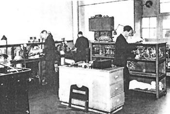
Approximately one-third of the main shop, which was 186 ft. long by 47 ft. wide, was used for component inspection, rectification, and the storage of components and sub-assemblies. Following the small-component store was a rebuild section and storage compound for the larger components such as cylinder block and crankshaft assemblies. The assembly line for the rebuild of complete engines extended from this point to the despatch bay. On one side of the despatch bay was a dynamometer test bed and on the other side offices for the foreman, storekeeper, and clerical staff. The fuel injection equipment room was in an extension of the main shop, adjacent to the office block. All work benches were fitted with aluminium tops and the shop floor was tiled. Heating was by blower fan steam radiators and the general shop lighting was supplemented by extensive lighting over the benches.
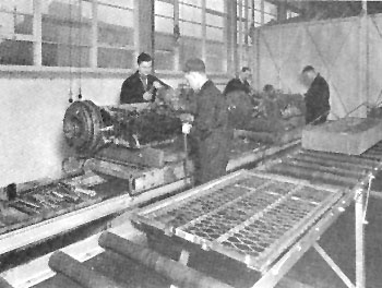
An overview of the DMU engine shop. Storage racks separate the rectification and rebuild sections.
Stripping and Cleaning
When an engine was received in the stripping annexe, equipment such as the fuel pump and starter motor were removed, and the engine was then passed through a twin-chamber high-pressure detergent spray washing plant for external cleaning (pictured right). The large chamber of the spray booth was 63in. by 75in. by 10ft. long and was capable of taking any completed diesel engine of vertical or horizontal type up to 950hp. Two Girdlestone pumps each delivering 300 gal. per min. at 60ft. head supplied the multi-spray cleaning nozzles. Another pump was provided for emptying the slump. The spray booth had a 1,000-gal. capacity sump and the steam heating of the solution by a steam coil was thermostatically controlled.
This initial cleaning was followed by dismantling of the engine into its sub-assemblies (pictured left). These were loaded into trays and passed on the roller conveyor through the smaller chamber of the spray booth which measured 51in. by 51in. by 10ft. long. Sub-assemblies were then completely dismantled at benches alongside the conveyor, the components loaded into baskets, and thoroughly washed and cleaned and carbon removed in a steam heated bosh. Three boshes were installed, two measuring 66in. by 72in. and one 42in. by 72in. These were fitted with a Keith Blackman 6in. blower and 36in. fume extraction fans. In the transfer from the stripping section to the main shop, the clean components were divided into eight streams, comprising cylinder blocks, pistons and connecting rods, auxiliaries, oil pumps, crankshafts, cylinder heads, crankcases, water pumps, manifolds and covers.
All loose studs, bolts, and nuts were dropped into a container, and after sorting into respective sizes returned to stores. The recovery percentage was high and the job was carried out by disabled personnel.
Replacement of Defective Parts
In the main shop inspection of the parts, covering visual, dimensional, and hydraulic pressure testing as required, was the first operation. Paint colour coding was used on each part by inspection to identify parts which may be refitted, rectified, or scrapped. Useable parts passed immediately to the sub-assembly stores, and replacements for scrapped parts were drawn on the inspector's authority from the works main component store. This system ensured that for each engine received a complete set of parts was available in the sub-assembly stores when required for the rebuild.
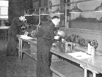
The next image shows the initial examination of the crankshaft on the sub-assembly line. The final image shows the honing of the 130mm dia. cylinder liners on a Delapena machine. The floating vertical shaft could be swung to any position over the work table.
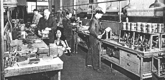
With the exception of certain partly-worn items, such as cylinder blocks, pistons and connecting rods, which by matching could be used for a further period, no attempt is made to rebuild the engine from the same sub-assemblies originally used. Pictured below is the piston sub-assembly section.
The inspection bay was well equipped with the special tools, gauges, and a water test fixture required for each engine type. All crankshafts were examined on a Fel-Electric magnetic crack detector, and a Hanovia ultra-violet-ray lamp was used for crack detection on smaller components. Valve springs were loaded and measured on a Britool dial-reading spring tester.
Racks and bins at the end of each inspection bench were used for the storage of parts requiring rectification. If welding, machining, or crank regrinding was required the parts were sent into the main works. Equipment was installed in this works in 1959 to investigate the extent to which electrochemical means could be used in the building up of worn parts. This equipment used the Dalic process of metal depositing.
Fuel-Injection Equipment
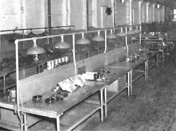
The fuel pump, removed from the engine immediately after receipt at the works, was sent along with the injectors to the fuel-pump repair shop (first image). Here was a "clean" room, 35ft by 27ft, with fitted benches and cupboards on each side and the calibrating machines and storage racks in the centre. The floor, benches and racks were linoleum covered. To secure maximum cleanliness all pumps and injectors were dismantled and cleaned before being brought into the "clean" room. Each set of cleaned parts was delivered in a tray provided with a socket for each component. Pump plungers and cylinders were first tested for rate of leakage on a Merlin comparator, and injector valve seats were ground and lapped on a Merlin Servicemaster.
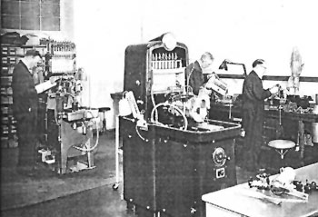
Each bench assembly station was fitted with an air-pressure cleaning nozzle discharging into a fixed tundish. The tundish was connected by trunking to an extractor fan, thus ensuring immediate removal of dust and foreign matter. Plastic hoods were used to cover all equipment until required for immediate use, and on the benches were roller-mounted canvas covers for the overnight protection of work in progress. For pump calibration there was a Merlin Calimaster and a Hartridge test machine (second image); and on the injector bench were three C.A.V. hand-pump test units.
Rebuild and Testing
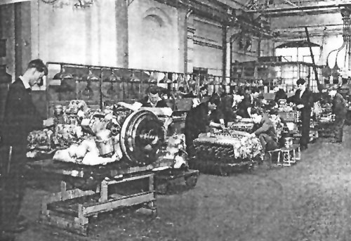
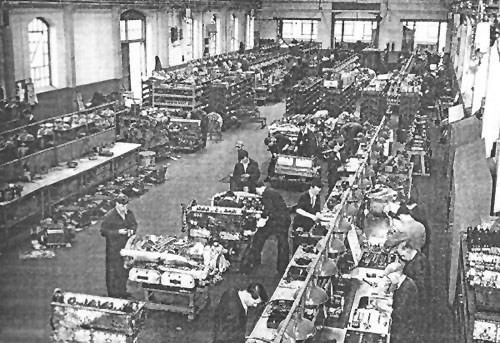
For the rebuilding of complete engines the crankcase-cylinder block forming the main carcase was mounted on a portable stand, and ten of these stands formed the assembly line (pictured right). The portable stands provided for flexibility in the progress of an engine along the line, according to rebuilding priority. Movement of engines was by a battery electric pallet transporter. From the accumulated stock of components in the repaired detail storage the sub-assemblies were made up and then transferred to the assembly storage racks situated at the end of each line in readiness for final assembly. A continuous bench at the side of the track was used to keep equipment off the floor during assembly. For the final assembly a series of portable erecting stands were arranged across the ends of the eight belt lines. Erection was performed in four stages. Each stand and unit were moved to the end of each pair of belt lines for the respective sub-assemblies to be erected. Patrol inspectors on the line ensured that the required high standard of cleanliness and workmanship were maintained, and that the complete build is to specification requirements.
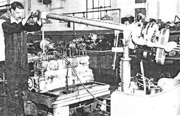
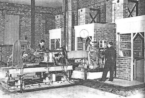
At the completion of the rebuild the engine, fitted with auxiliaries, was run-in and load tested on a Heenan & Froude type DPY5 hydraulic dynamometer.
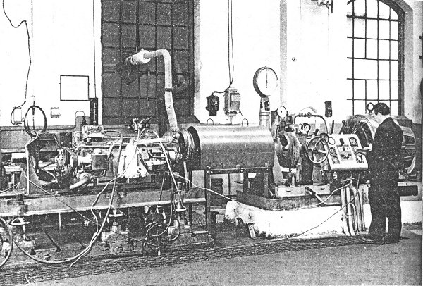
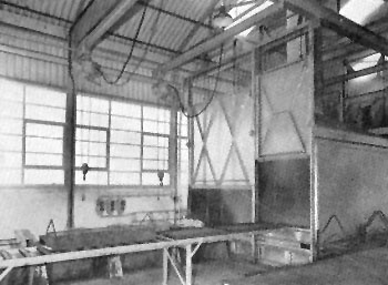
This was suitable for testing engines up to 640hp. Driving through the brake was a 35 h.p. 300-800rpm variable-speed electric motor (it can be seen on the right of the control panel). This was used to motor the engine for a short period to remove initial stiffness and circulate the oil. Following a run of 30 min. at no load the engine was run for 2 ½ hr. with progressive load increments at speeds between 1,000 and 1,800 r.p.m. This was followed by a series of tests over the same speed range at the maximum rated output for each speed. Fuel consumption was checked with a Flowrater meter, measuring the rate of fuel flow in c.c. per sec. The test bed was equipped with a 400-gal. fuel tank, and a 100-gal. cooling-water header tank fitted with a Drayton automatic temperature regulator. Lifting the engine on and off the test bed and on to the transporter vehicle after painting was by a 1 ton capacity overhead travelling crane. This single test bed was soon inadequate to deal with the flow of engines then being handled by Derby, and by 1959 additional test beds were being installed in an adjacent building. The first of these is pictured in the final image.
In addition to the overhaul and rebuild of complete engines, an increasing amount of component repair work was carried out for other diesel depots in the London Midland Region. A stock of reconditioned components was held in store ready for immediate issue as replacements when defective parts are received. The defective parts were then reconditioned and returned to store, or if not repairable new parts are issued as stores replacements.