
Gearboxes
Introduction to Epicyclic Gearboxes
A DMU engine cannot be directly coupled to the rail wheels for the following reasons:-
- It cannot start from rest when under load
- It will stall at a certain minimum speed of revolution
- Insufficient torque is produced at low rotational speeds
To overcome the above difficulties a speed change gearbox is used on mechanical transmission sets, positioned between the engine and the bogie.
The gearbox ensures:-
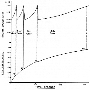
- The full engine output is available over its designed working speed range (in the case of BUT 150hp engines 1,100 to 1,800 rpm).
- High torque is available at starting
- The torque is capable of smooth variation
- Minimum duration of loss of tractive effort when changing gear.
In short the gearbox provides a method of obtaining from the engine the right power at the right speed to work the train.
Epicyclic (or 'Wilson') gearboxes were used. Four gear ratios and 'neutral' may be obtained with this gearbox. Top (or fourth) gear involves all the gearing rotating as one unit, the other three gears being indirect, i.e. through gear trains.
Each indirect gear has its own air piston operated balanced brake, which consists of two concentric bands, one within the other. They are wrapping in action, i.e. the friction of the brakes on the drums tends to increase their grip.
The running gear is what is known as the compound epicyclic type, this is best understood regarding the first gear train as being the basic train. Referring to the diagram below, the sun-wheel of this train is integral with the output shaft, known as a planet carrier. The planet wheels in turn mesh with the first speed annulus.
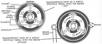
When this is held stationery by its brakeband, and input shaft is driven, the planets are caused to roll around inside the annulus, carrying with them the output shaft at a speed determined by the reduction ratio of this gear train.
By means of the other epicyclic trains the annulus of the basic train is caused to rotate at certain fixed increments of input speed, which has the effect of producing the other ratios.
Movement of the driver's gear selection lever energises an electro-pneumatic valve which directs air to the appropriate brake air cylinder. This raises the piston and through a toggle-mechanism applies the brake. The pistons for nos. 1 - 3 are of varying size, according to the torque which each brake has to restrain.
The brake linings wear slightly, but this is compensated by an automatic adjuster.
Top (or fourth) gear is obtained by a clutch which locks together two of the running gear elements and causes all the gearing to rotate as one unit. In top gear there is no wear in the intermediate gear trains, and this is one reason why coasting was always to be done in top gear. The drive in top gear is direct from input to output. Running in neutral would cause the compounding of the gear trains in the opposite direction, thus overspeeding gear three.
The gearbox utilises air pressure, from the main compressed air supply.
Lubrication is by means of a gear-type oil pump on the input side.
The need to pause for two seconds after selecting gear before opening the throttle was very important.On selecting a gear the appropriate electro-pneumatic valve will be energised; this will allow air to act on the piston for that gear. The piston applies the brake band and the desired gear is obtained. Two seconds was necessary for this sequence of operations, ie for air to operate the piston and the annulus to be stopped before the throttle is opened and torque applied.
It was possible in certain circumstances for wear on a brake band to occur faster than the automatic adjuster can overcome it. In such cases engine racing would occur when accelerating in the affected gear, and the tachometer would persistently show 'change up' before the correct rail speed for that gear had been attained. It could be corrected by a toggling procedure.