
Automatic Warning System
The Automatic Warning System is commonly referred to as the 'AWS'. This section describes British Railway's own system, not the WR ATC which it inherited from the GWR and many WR DMUs were equipped to operate with.
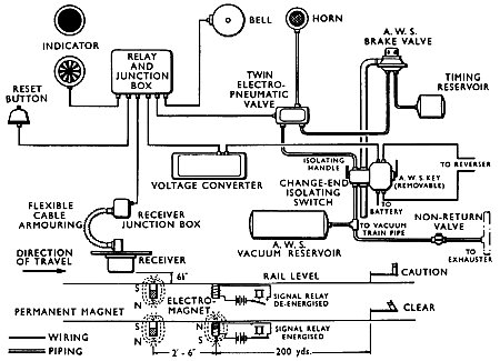
The BR system works on the principle of magnetic induction. When a distant signal is at 'caution', the permanent magnet situated between the running rails alters the receiver setting on the vehicle, causing the AWS horn to sound and the initiation of a full brake application after a short delay. Cancelling or acknowledging the 'caution' indication by means of the 'reset' button provided, silences the horn and causes the visual indication to change from all black to yellow and black. If the distant signal is at 'clear' the electro magnet is energised, which restores the receiver setting to its normal position, the action of which causes a bell to ring in the driving compartment for three seconds.
AWS features in a British Pathe newsreel demonstrated on a Class 127.
Method of Operation
In this system two magnets are fixed centrally between the rails, 2ft 6in apart, generally 200 yards on the approach side of the signal. The first contains a permanent magnet with its south pole uppermost, and the second is an electro-magnet. The electro-magnet is 'dead' when the distant signal is at caution and 'alive' with its north pole uppermost when the signal has been pulled to clear. The pole faces of the magnets are at rail level.
In addition to the above, permanent 'caution' magnets are provided in the outlet roads from depots to test the equipment before going into service.
The vacuum in the AWS reservoir of the DMU is created by exhausters operating through a non-return valve. When the change-end switch is in the 'on' position the change-end switch connects the main batteries to the voltage converter which supplies 12 volts dc to the AWS circuit. The change-end switch also connects the train line to the contacts of the reverser key. The horn is operated by vacuum and controlled by an electro-pneumatic valve.
The upper side of the diaphragm in the AWS brake valve is connected direct to the vacuum train pipe. The underside is connected to the vacuum timing reservoir and controlled by the electro-pneumatic valve. In the normal position the brake valve is balanced by vacuum on both sides of the diaphragm, and a light coil spring is fitted on top of the valve to assist it to close. When the brake is applied through the action of the AWS, air is admitted to the underside of the diaphragm, at a controlled rate, which upsets the balance and causes the valve to lift, admitting air to the train pipe with a resultant brake application.
The receiver consists of a small permanent magnet pivoted at a central point and carrying contacts which act as a two-way switch. When running between signals the receiver N contact is in its normal closed position, forming a circuit to the electro-pneumatic valve which controls the vacuum and atmosphere as described above. When the distant signal is at 'caution' the receiver passes over the south pole of the permanent magnet, the receiver N contact opens, and after one second the electro-pneumatic valve is de-energised and operates to connect the horn to the vacuum reservoir, thus causing it to sound; also air is admitted through a restriction in the electro-pneumatic valve to the timing reservoir and brake valve. Then the AWS brake valve operated and admits air to the train-pipe. The horn can be silenced and any brake application cancelled by operating the 'reset' button, which restores the receiver contact to its normal position (N contact) and resets the solenoid in the electro-pneumatic valve.
When approaching a distant signal in the 'clear' position the electro-magnet is energised, creating a N magnetic field. In this case the receiver contact changes over as before through the influence of the permanent magnet, and then changes over as before through the influence of the permanent magnet, and then changes back again through the influence of the electro-magnet. If travelling at more than 1 1/2 mph less than one second will elapse between changes of the receiver contact, and the solenoid in the electro-pneumatic valve would not be de-energised to cause the sounding of the horn or apply the brakes, but the changeover of the receiver contact picks up relays which, in turn, cause the bell to ring for 2 seconds.
In addition to the audible signals of horn or bell a visual indicator is provided. When the receiver passes over the permanent magnet, current passes to the indicator to turn it to, or keep it at, all black. If the distant signal is at 'caution' and the 'reset' button operates to silence the horn, the indicator automatically changes to display yellow and black spokes, and this is maintained until reaching the next set of magnets in the track, which is a constant reminder to the driver that the last signal was in a 'caution' position.
It should be noted that the operation of the 'reset' button will only change the indicator from black to yellow-and-black after receiving a 'caution' warning.
EP Valve Leakage Test

This diagram was found in some totally unrelated DMU maintenance notes, and shows how to conduct a leakage test on the Electo-Pnuematic (EP) valve.