
Park Royal Railbus
Description
Power Underframe
The welded steel underframe, fabricated from 9 in. x 2 in. x 3/8 in. rolled steel channel, consisted of two main solebars, end cross-members, two intermediate longitudinal members and five main cross-members; the main connections between cross-members and longitudinals were plated above and below. Additional support members were included where required to carry the main running units, and also included wide gusset panels at all junctions and diagonal bracing at each end. The side-bearing spring anchorage points were built on to the solebar at each corner combined with the axlebox safety guides. The end cross-member at the final drive end carried the final drive torque reaction member and was stiffened to withstand the extra load. The power frame and underframe sections were supplied by John Thompson (Motor Pressings) Ltd. Twin interconnected fuel tanks, with a combined capacity of 70 gallons were mounted at the driving axle end of the main underframe. Tank fillers were provided on each side of the vehicle. For the heaters a separate tank held 105 gallons, and was mounted with the Smiths heater longitudinally under the body frame at the non-driving end. In 79972-4 these were cylindrical, on 79970/1 these were rectangular.
Suspension & Brakes
British Railways standard design of diesel railcar steel disc wheels (of 3 ft diameter) and axles were used. These were supplied by John Baker & Besemer Ltd. The special double-row spherical SKF roller-bearing axle-boxes used did not embody horn guides, but were located entirely by the side bearing leaf springs. The axlebox incorporated safety guide lugs which worked in conjunction with the guide plates on the underframe to limit longitudinal or transverse axlebox movement should a spring fail. The side bearing springs, longer and with a slower rate than was ordinarily used on railway stock, had a solid buckle shrunk on and secured by wedges over the spring leaf centre locating dimples. The buckle was clamped below the axlebox by a separate cap secured by four high tensile studs and nuts, and was located in box and cap by pegs. The spring was anchored by an eccentric pin at one end, the other end bearing against a case-hardened guide and wearing plate to allow spring movement on deflection. This layout provided positive location of the axle and box while giving a soft ride by obviating all but inter-leaf friction within the spring layout. Laminated and coil springs were supplied by Jonas Woodhead & Co. Ltd.
Orthodox wheel rim clasp type brakework was fitted, with fully compensated rigging, each axle set being mechanically independent. B.R. pattern brake blocks and permanent heads were used for ease of replacement from stock; adjustable by conventional stepped-hole adjuster plates. The main cross shaft of each axle set was operated by one direct-acting air pressure cylinder, linked to the lever by a yoke to permit movement of the cross shaft by the handbrake. Lever-type hand-brake controls were of the drum type giving multi-pull operation in the event of wear in the system, and quick and complete release in one movement. Both Neates type handbrake levers, one in each cab, were connected by flexible heavy duty cable to a cross lever on the under-frame, to permit free movement of the body from the underframe. The cross lever was in turn linked to each brake operating cross shaft, allowing either handbrake lever to operate all brakes.
The Clayton Dewandre air brake system, of the direct acting type, used twin 6 in. dia. brake cylinders, one to each axle set, connected via relay valves to the train pipe. The relay valves principal function was in the event of air pressure failure, when separate emergency reservoirs, one for each axle set, were brought in for brake application. At all other times these reservoirs were charged from the main reservoir and isolated by the relay valve. The driver's brake valve, with removable handle, was of the progressive type, the distance that the handle was moved towards the applied position determining the train pipe pressure. Dead-man's handle and passenger emergency valve were also fitted. The first operated through a 6 second delay device from the throttle control, and in addition to the brake application, the engine returned to idling and the gearbox to neutral. The second was a simple lever type cock in the vestibule on the partition at cant level. This admitted air pressure direct to the train pipe, and required the release cord to be operated to reset it. All brake equipment auxiliary valves and fittings were positioned on the outside of the solebar to facilitate servicing.
Transmission and Control Gear
The engine, mounted adjacent to the non-driving axle, was the B.U.T. 150 h.p. "A" type (AEC 220) 11.3 litre 6-cyl. unit, with 20 in. fluid flywheel. This drove via a Hardy Spicer cardan shaft through a free wheel, the Self-Changing Gears R14 four-speed air operated epicyclic gearbox. The drive from the box was transmitted by another cardan shaft to the axle-mounted B.U.T. air operated final drive unit, which incorporated the forward and reverse gearing. The final drive ratio was 3.36 to 1 and the gearbox ratios were: 1st, 4.28 to 1, 2nd, 2.43 to 1, 3rd, 1.59 to 1 and 4th, 1.00 to 1. Vehicle 79974 had a newly developed CAV fully automatic control. The engine was cooled by a side mounted radiator unit with ducted fan, shaft-driven by a right-angle drive unit on the engine.
Electro-pneumatic control, of B.U.T. design, was used for the engine and transmission, employing high pressure (80 p.s.i.) E.P. valves for throttle motor and forward and reverse control, and low pressure (65 p.s.i.) E.P. valves for gear selection and the deadman's control. The throttle controller, which incorporated the hold-down deadman's device provided for four throttle positions and idling. The air compressor was driven by multiple vee-belts from the input side of the gearbox.
The 24v., 200 A-h Nife batteries, with provision for external charging, were mounted in two containers slung one on each side of the underframe. The CAV AC8 a.c. generator was also belt driven from the input to the gearbox, at 2.8 times the engine speed. At engine idling speed the minimum output was 30A., with an output of 50A maximum at the governed engine speed of 1,500rpm. A CAV UN411 germanium rectifier was used to rectify the a.c. current.
Body
The principle of the main body suspension necessitated the use of a separate integrally constructed body unit. The body framing was based on a welded steel channel section body underframe which, combined with the stressed bodysides and roof structure, resulted in a self-supporting box structure of the necessary rigidity. To this were mounted four triangulated suspension brackets, positioned to clear the four outer corners of the main power underframe, and with their thrust faces set at 45 degrees to the underframe top face. Located on these faces by two dowels were the top reaction and location plates of the main suspension coil springs, the bottom ends of which were placed in similar plates carried on threaded eye bolts passing through the spring and body bracket and fixed in trunnion blocks mounted to the power frame. The vertical body movement on loading was transferred to angular compression of the springs and as the load increased the spring angle more nearly approached the vertical, thus varying the spring rate to suit increasing load. Free vertical oscillation was damped by four Woodhead-Monroe telescopic hydraulic shock absorbers mounted between body and power frame, and lateral and longitudinal movement was prevented by four "Ferobestos "-faced brackets on the power frame registering inside corresponding box members in the body. These body stops came into use on braking or acceleration and on sudden changes of direction and also enabled the vehicle to be towed. As the railbuses were intended just for single unit operation, only spring loop type buffers were fitted, attached to the body underframe. A spring hook was also fitted to the body frame for emergency towing and depot use.
The structure was based on a welded steel channel section underframe with reinforced cross-members at the body mounting points. Cast alloy brackets and a 3/16 in. thick aluminium alloy member, connected the main pillars, which were of robust "H" section extruded aluminium alloy, to the solebars. Internally, fitted stress panels of 14g aluminium alloy were solid riveted to the framing from seat rail to waist with a 3/16 in. one-piece alloy cove from seat rail to floor forming a stressed skin. The vestibule and doorways were formed by floor-to-cant stress panels. To complete the box structure the roof unit was bracketed to the pillars through the full length cantrail lower channel. The main roofsticks were of top hat section, flanges upward, solid riveted to a shaped cove panel in mild steel extending the full length of the roof each side and riveted to the lower cant channel and pillars. The roof exterior panels were of aluminium alloy overlapped and double row solid riveted to the sticks forming part of the stressed skin. Shaped domes incorporating the destination boxes were fitted at each end.
Aluminium shaped end panels in one piece, incorporating the code lamps and route indocator boxes, and 16g aluminium alloy main side panels in one piece from doorway to front quarters, were secured to the pillars by coverstrips and blind rivets. This was after the outer face of the inner stress panels had been asbestos sprayed, as was the roof interior before the composition roof lining panels and aluminium cove panels were fitted. The insulation and asbestos was supplied by JW Roberts Ltd.
Interior
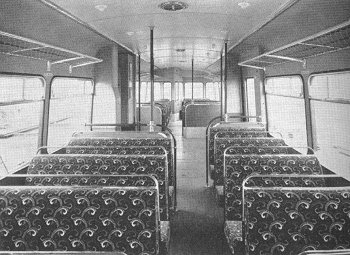
Below each doorway was an 11 in. deep steel stiffener. The floor was formed of corrugated extruded aluminium alloy planking bolted to the main body underframe bearers. This was Limpet asbestos sprayed to fill the corrugations and to a depth of about 1/4 in. over; 1/2 in. resin bonded ply was then laid and covered with dark blue linoleum. Floor traps over engine, gearbox and final drive permitted servicing from the saloon where necessary. The seating, for 50 passengers, was arranged in a 2 + 3 basis each side of the vestibule with the seats facing the end of the car in each half. Bus type tubular frames were used, supplied by GD Peters & Co Ltd, fitted with Dunlopillo cushions and Hairlock squabs, trimmed with blue patterned cut moquette.
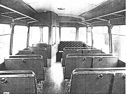
The interior finish of the saloon was carried out in Vynide leathercloth, blue up to the waist and grey above up to the top of the roof cove. The centre lining of the roof was in Limpet hardboard, painted eggshell grey. Light parcel racks, with netting and aluminium frames were fitted above both sides of each saloon, supplied by Deans & Sons (Yorkshire) Ltd. Car heating with filtered air was by a Smiths heater, which also supplied the cab screen demisters. Five roof vents were also fitted for air extraction. Interior lighting was by a double row of open reflector lights positioned over the seats.
The power-operated single sliding doors (supplied by GD Peters & Co Ltd) were controlled by the driver and operated by direct air cylinders electrically switched. They also had a release cock at the doors for release in an emergency or depot use. They opened into the 10ft 8in vestibule. Waist height partitions, with a handrail on top, formed a partition between vestibule and saloons. In the vestibule was trunking enclosing the second of the engine exhaust silencers, which discharged at roof level. Inner and outer trunkings were used, asbestos lined internally, with air spaces between silencer and inner trunk, and between inner and outer trunks, the inner space being open top and bottom.
All Widnes main side windows, manufactured by Hallam, Sleigh & Cheston Ltd, had double top sliding unit windows framed in aluminium alloy and rubber glazed in steel pans. Inside window ledges were avoided by bringing the rubber glazing strip flush with the body side. Beclawat full-drop windows were fitted in each cab and in the saloon on the opposite side to the cab window adjacent to the fixed corner windows which were radiused to the body contour.
The driver's position was reached from the saloon and separated by full height partitions, glazed to the same height as the main windows. Controls were orthodox, one knee-type desk with left-hand throttle control and dead-man's device, right-hand gear selector with forward and reverse lever below and brake handle. Mounted in the front dome on the opposite side of the car to the cab, and accessible while leaning out of the full drop window was a deadman's cancellation button for use when single line working was in force.
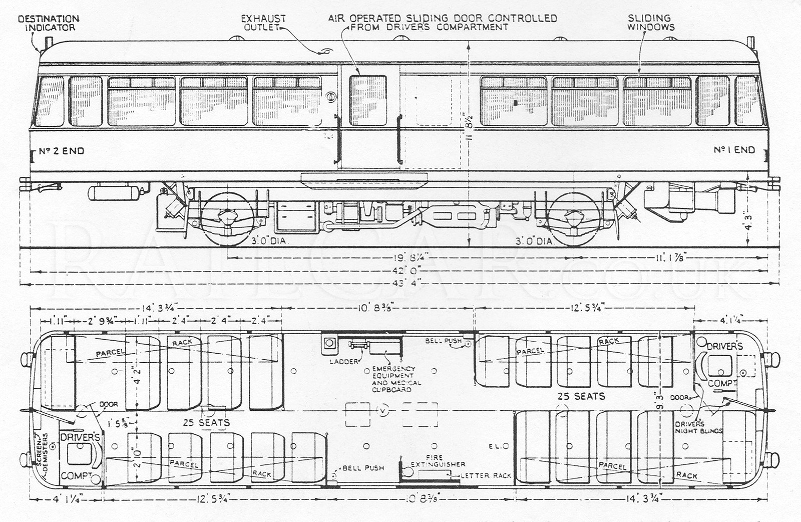
| Overall length | 43' 4" |
| Length over body | 42' 0" |
| Width over body | 9' 3" |
| Overall height - laden | 11' 8 1/2" |
| Floor height from rail | 4' 3" |
| Wheelbase | 19' 8 1/4" |
| Wheel diameter | 3' 0" |
| Tare weight | 15 tons 0 cwt |
The two built for the ScR had a form of automatic folding passenger steps.