Wickham Railbus
The Pneumatic Suspension fitted to Sc79969
From 'Diesel Railway Traction', September 1959.

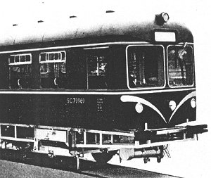
The last of the Wickham railbuses was fitted with a form of pneumatic suspension evolved by Wickham in collaboration with the Andre Rubber Co. Ltd (who worked with the General Tyre & Rubber Co. Ltd. of USA. The pneumatic portion came from the general compressed air system of the railbus, and the air-control equipment was by Westinghouse Brake & Signal Co. Ltd. In overload conditions the gross weight of the railbus was about 18 tons, of 4 1/2 tons per group of pneumatic springs.
Twin-Cell Air Spring per Wheel
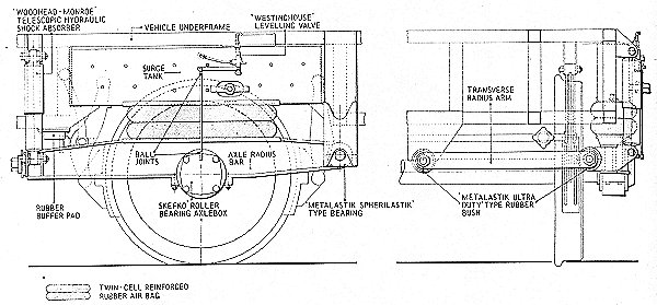
In the fifth railbus the usual Wickham axle radius control was replaced by members which were of deeper section and extended to double the original length. Over the mid-length of each radius bar, centred above that part to which the SKF self-aligning roller-bearing axlebox was attached, was a flexible reinforced rubber air bag consisting of two elongated and interconnected cells bonded securely together and to upper and lower mid-steel location plates. Above the air bag was a welded steel rectangular air surge tank, built in to form part of the underframe. Each air bag had internal bump rubbers as an additional precaution against trapping.
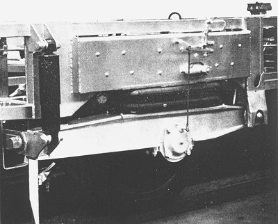
Mounted on and connected to the surge tanks were Westinghouse levelling valves with actuating levers and connecting rods to the axleboxes. These valves were developed to control the air inlet and exhaust of the springs so that the neutral position of the axle under static load conditions remained constant, and so that the floor-to-rail height did not vary with extremes of vehicle loading. Steel-framed expanded metal guards protect the levelling valves and connecting rods from accidental damage.
The frequency of any air-springing system is related to the air volume and pressure. With the air spring dimensions fixed, the load-carrying capacity or 'rate' of the spring depends on the available air pressure. Approximate static pressures for the Andre-Westinghouse system as measured on the railbus were:
for tare weight only... 44lb. per sq. in. (3.09 kg. per sq. cm.)
for tare plus load... 59lb. per sq. in. (4.15 kg. per sq. cm.)
for tare plus overload... 74lb. per sq. in. (5.20 kg. per sq. cm.)
The surge tanks were provided to ensure the necessary total air volume. Each flexible air bag had a volume of 660cu. in. (10.81 litres), and together with the surge tank capacity this made the total available volume 3,160cu. in. (51.8 litres) for each spring. The air spring alone had a frequency of approximately 87 cycles per minute, that is a periodicity of 0.69 sec., but the effect of the rubber bushes in the linkage was to raise slightly the actual frequency of the system.
Air at 90 to 110lb. per sq. in. (6.3 to 7.75kg. per sq. cm.) from the basic system of the railbus normally passed through a non-return valve and thence into a special reservoir for the suspension system. At the reservoir outlet was a filter, and following this were air lines communicating with the supply cap nut in the top of each levelling valve. Control of delivery to, or exhaust from the air springs was by a port in the side of the valve body, from which a pipe was led to the surge tank.
When the actuating lever was horizontal the passages through the valve were closed and air was sealed in the respective spring. Upward movement admitted air and downward movement exhausted it. In this manner the control valve was able to compensate for variations in the vertical distance between the vehicle body and axle by increasing or decreasing the air pressure in the spring. In addition to varying spring stiffness to suit the load conditions, this had the effect of maintaining a constant floor height above rail level as long as pressure was held in the air reservoir. A two-stage calibrated valve controlled the rate of air flow.

Dampers
The energy storage capacity of the air springs absorbed vertical loadings caused by track irregularities and rail joints, without allowing vibration to affect passenger comfort. Dampers were considered to be essential to any passenger carrying vehicle suspension, and here vertical movement at the outer extremity of each radius bar member was controlled by a Woodhead-Monroe telescopic hydraulic shock absorber with 8-in. total movement, which ensured progressive damping of the suspension. A transverse radius arm relieved the air bags of any loading due to side thrusts between wheel and rail.
The main pivot of each axle radius bar was a Metalastik rubber bushed bearing. Metalastik Ultra-Duty bushes were used at the ends of each transverse radius arm, the inner ends being pivoted to the underframe cross members only 3 in. from the centre line of the vehicle. By this use of rubber frictional wear at the suspension pivots was eliminated without the need for lubrication or any other form of regular maintenance.
A rubber buffer pad limited dynamic upward axle movements, and also limited the distance by which the chassis frame was lowered when the air springs were deflated. The extended axle radius bar acted as a beam when engaged with the buffer pad and when maintaining lateral stability under conditions of wheel flange action; consequently it was of substantial proportions.

Summary
Description
Interiors
Suspension
Numbering
Operations
Elliot Track Recorder
Images
Details about the preserved Elliot Wickham railbus can be found here.


