
Heaters
Most vehicles were fitted from new with Smiths heaters, a few had a similar type manufactured by Dragonair, these were latterly replaced by the Smiths version due to recurring problems.
In later days the Smiths heaters were colour coded, the fan end being painted one of three colours:
| Colour | Heat | Hand |
|---|---|---|
| Red | 50,000 BTU | - |
| Blue | 40,000 BTU | Left |
| Green | 40,000 BTU | Right |
The warmer 50,000 BTU units (differing only by their fuel pumps) were fitted to vehicles which only carried one heater per vehicle such as Class 108s. Vehicles which carried two heaters generally required one of each hand, as the glow plug is always required to be in the side facing outwards for ease of access.
The following resources on heaters are available:-
Articles
Basic description of how heaters work
A list of the heater types fitted to vehicles when new
Training Documents
Western Region Operating Staff booklet
TSU 89/99 Generating Equipment & Combustion Heaters
Manuals
Smiths Spare Parts Book
CEPS 24 - Overhaul and Repair of Smiths Combustion Heater
WOSS 830/4 - Combustion Heater Workshop Overhaul Standard Specification
Dragonair DVLA/80
Wiring Diagrams
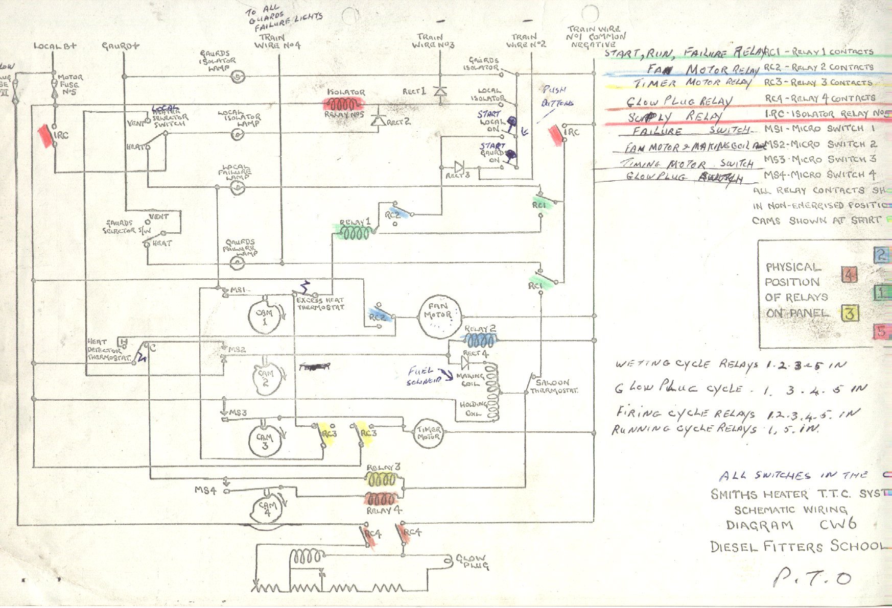
Diesel Fitters School - Diagram 1 -
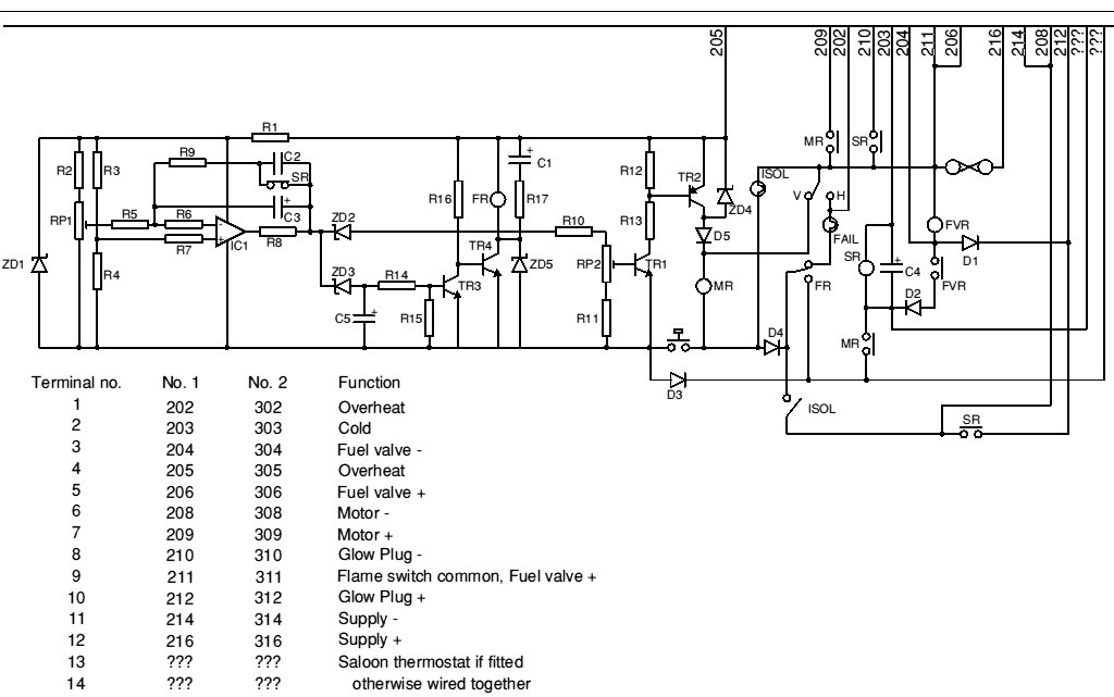
Diagram 2
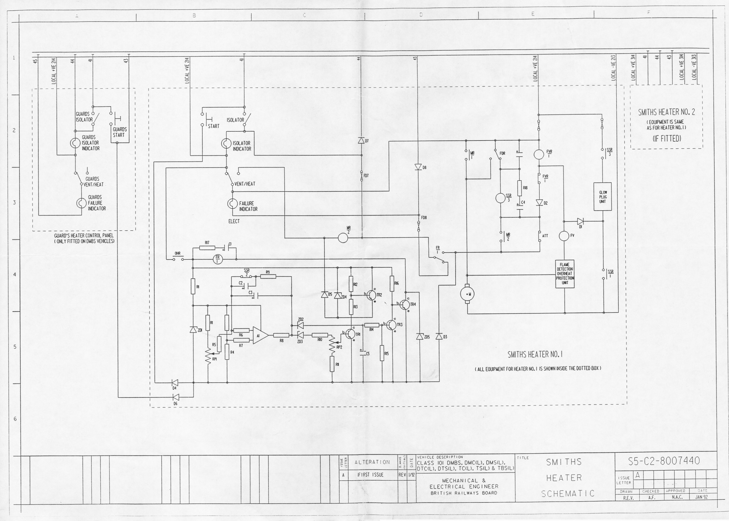
Schematic - January 1992 (for 101s but applicable to others)
Cab Control Box (courtesy of John Joyce)
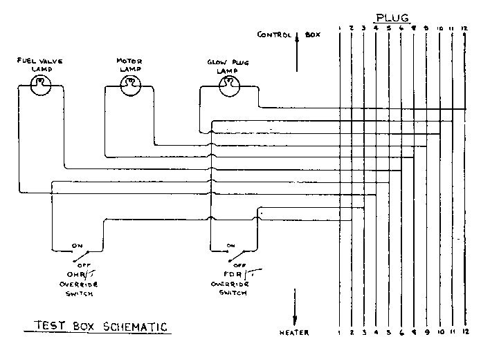
Heater Test Box (easy to make, and very useful in analysing faults)
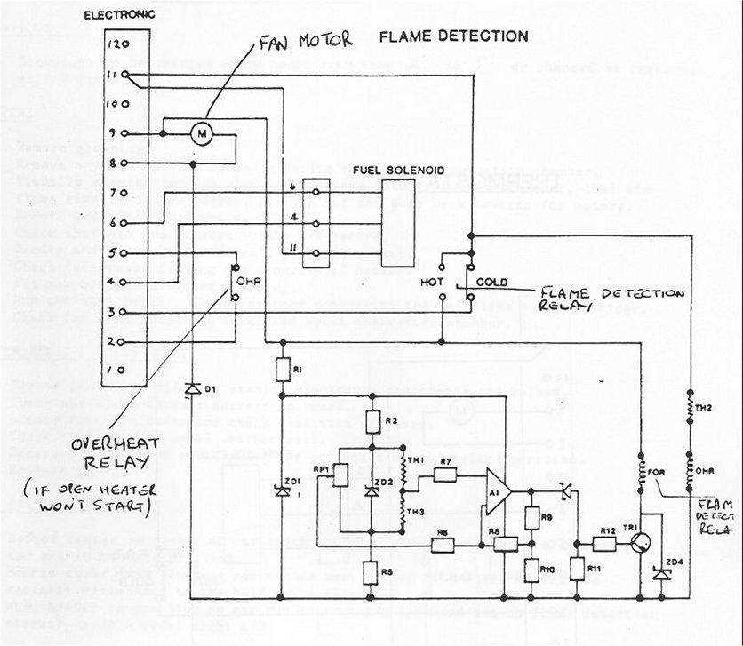
Flame Detection
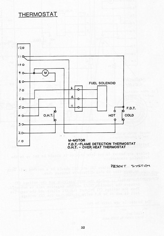
Thermostat
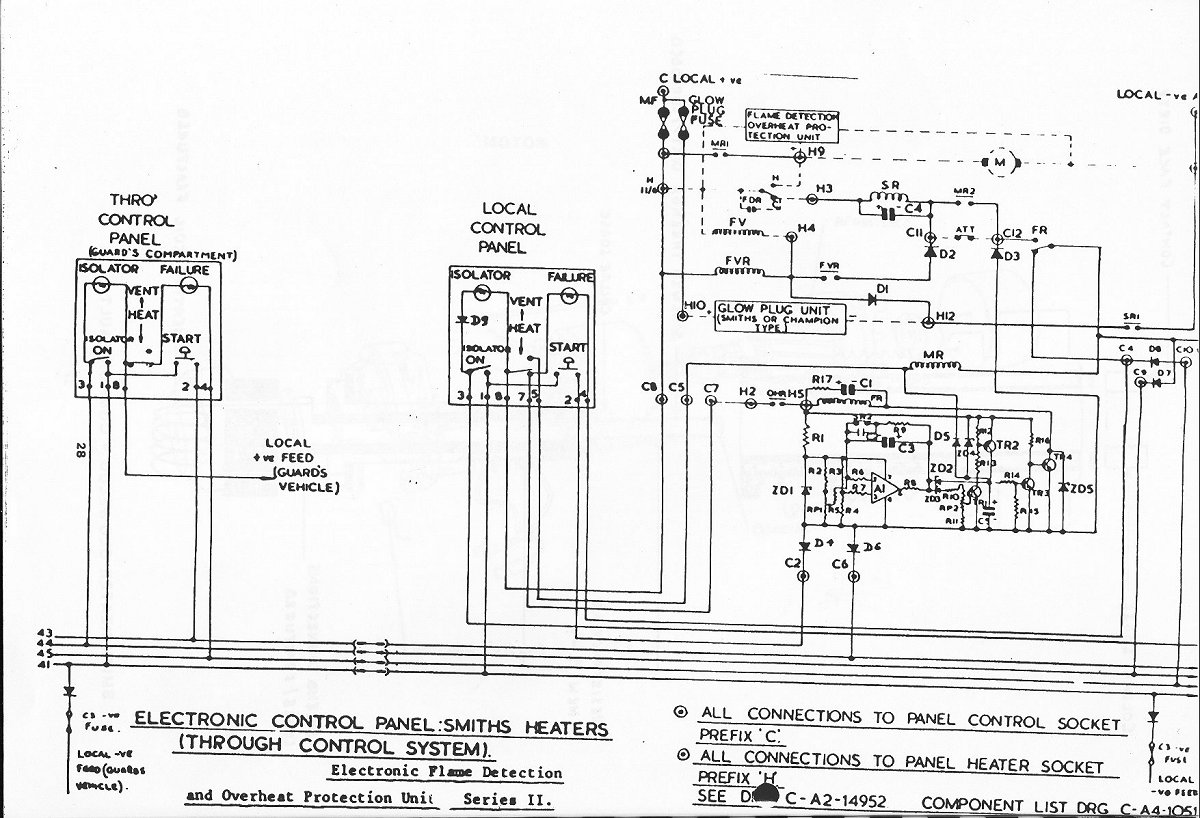
Through vehicle control system
Fault Finding
There have been many different variations of heater fault guides issued over the years. As examples here are two tables, one being basic and one more in-depth. They both look mainly at the heaters themselves.
There are also fault finding flow-type charts, which include the control systems, although theses are from a very dated drawing ("Diesel Office Ref: SK/CO/5/44") and deal with the clockwork/cam systems, although they are still of use. There is one for semi-automatic systems, and for through control systems there is one for heat and one for vent.
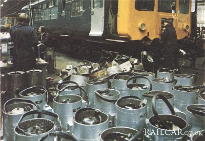
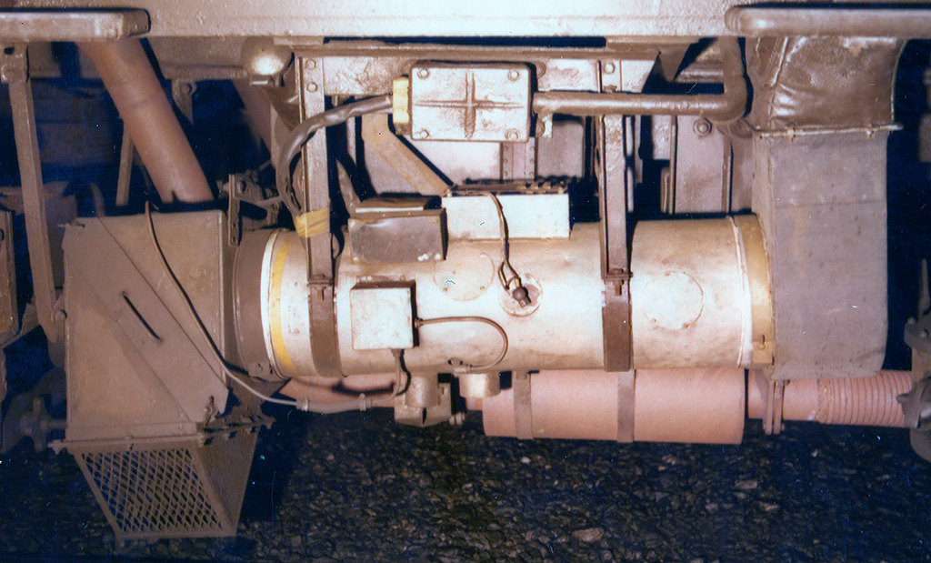
The image shows a mass of overhauled heaters await fitting at a depot, with more being worked on behind.
In 1977 BR determined they could reduce the number of electrical faults and improve the reliability of heaters by electrically insulating them from the vehicle. This was achieved by: a) using rubber pads on the mounting straps; b) inserting a short length of rubber tube in the copper fuel pipe; c) introducing an insulating bush at both ends of the heater. These were made of GRP and slid over the heater. When the heater was in position the bush was slid into the ducting at both ends to prevent metal to metal contact. Metal clamping brackets are then fitted around the bush and ducting.