
Heaters
Principles of Operation
The majority of DMU vehicles were built with what are termed combustion heaters with air being warmed in a diesel fired heat exchanger before being distributed through ducting in the coach. Often the air to be heated could be drawn from the atmosphere or it could be re-circulated from the vehicle, the choice between the two systems being governed by the operation of a simple flap valve in the air trunking.
The heat-exchanger completely separated the heated air supply from the exhaust gases resulting from the combustion of the fuel in the combustion unit.
This type of heater is almost self-contained, the only requirements being a suitable fuel tank and pipework and an external electrical supply. It is generally mounted beneath the floor of the vehicle, where it does not encroach on passenger accommodation.
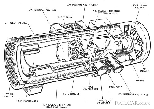
The principle components of the heater are shown in the sectioned diagram. The combustion unit comprises a fuel pump, a fan for combustion air, a fuel 'slinger' and a glow plug, all in a circular chamber which forms the combustion chamber. Air for combustion is drawn by the fan through the intake tube into the motor housing, past the fuel pump into the impeller inlet and from the impeller through a diffuser into the combustion chamber.
Fuel is drawn from the fuel tank by the pump and delivered through a small pipe into the periphery of the fuel 'slinger'. As this is rotating at approximately 3,500rpm the fuel is discharged radially in a finely divided spray which ensures a thorough mixing with the incoming combustion air.
Ignition of the mixture of fuel and air is by a glow plug when the heater is first put into operation from cold; once combustion has begun it is self-sustaining. The heat exchanger is formed from a continuation of the wall of the combustion chamber beyond the baffle, so placed as to confine combustion but to provide an outlet for the hot gases. Four radial ports lead from the heat exchanger through the heater-air passage to the exhaust outlet.
The air to be heated is drawn into the heater by an axial-flow fan. The cold air passes over the walls of the heat exchanger, from which it picks up a portion of the heat of combustion, and so through the action of the fan to the distribution ducting in the vehicle. It will be seen that there is no possibility of the hot air for warming the vehicle being contaminated with any of the products of combustion.
A single electric motor is provided to drive the fuel pump, the fan for combustion air, the fuel 'slinger' and the fan for hot-air circulation. By this arrangement the fuel quantity and the combustion-air quantity are in a permanently fixed ratio and, in a like manner, the volume of air circulated has a fixed ratio to the heat produced by the combustion of the fuel.
The heater is provided with safety features which protect it from the effects of mal-operation.
The starting procedure is completed by means of a timing mechanism which is automatically set when the main switch is operated. Within the mechanism are two sets of contacts, one set operating glow plug and the other set operating the motor. When the time cycle has been completed both contacts return to the open condition.
The sequence of operation is:
- Glow plug is switched on and comes up to operating temperature.
- Fuel valve opens and motor starts.
- Combustion starts.
- Flame detection operates and holds the fuel valve open and the motor on.
- Timed cycle complete. Glow plug, motor and fuel-valve contacts in time switch open.
The protective devices operated as follows:
- (a) Failure to ignite
- After completing the time cycle the heater will shut down, since the flame detector thermostat remains in the cold position.
- (b) The flame goes out
- Heat will die away, the thermostat will change to the 'cold' position and shut down the heater.
- (c) Overheat
- Excess-heat thermostat will shut off the fuel and cause heater to shut down.
The type of heater described has semi-automatic control. A fully automatic system was also used and was controlled by a saloon thermostat.