
Throttle Motor
Overhaul
by John Joyce
Tools
Nothing special - Whitworth spanners, screwdriver, hammer (of course), bench-mounted vice. New seals if required. Approx £2.50 each, x4.
1 - Air Cylinders
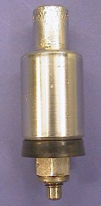
These can be serviced without taking the throttle motor off the vehicle, if the rest of the gubbins works. For each cylinder, disconnect the air pipe, and then undo the two nuts holding the cylinder to the main body of the throttle motor. Remove the cylinder / piston assembly downwards. Hold it in a vice, and undo the three nuts at the bottom to release the end cover. Remove the end cover, either by prising it off gently (don't damage the mating faces), or by pushing the piston downwards in the cylinder. It is also worth undoing and removing the air pipe adaptor to enable a thorough cleaning out. Don't lose the copper washer. Wash everything thoroughly in some solvent (paraffin, white spirit etc; diesel will do but smells and takes ages to dry) with a stiff brush. I cheated and shotblasted these to make the pictures look nice.
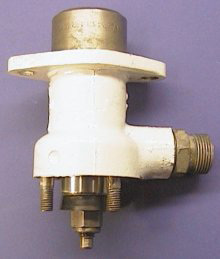
Now renew the rubber piston seal by holding the narrow part of the piston in a vice (not the widest part of it) and undoing the nut at the other end. Remove the seal and washer, clean everything up, and fit the new one. Note which way round the seal goes - the lip goes towards the nut as shown in the picture. Inspect the bore of the cylinder - it may be a little worn but shouldn't have any deep scratches on it. Now refit the piston into the cylinder, seal downwards (see second picture) and with a little lubrication (general purpose oil) and fit the end cover. It will need some form of gasket - gasket paper or thin cardboard will do for this. The specimen overhauled had two cut from the cover of a defect book!
Refit to the underneath of the throttle motor and repeat for the other three cylinders. There is no need for a gasket between the cylinder and throttle motor body.
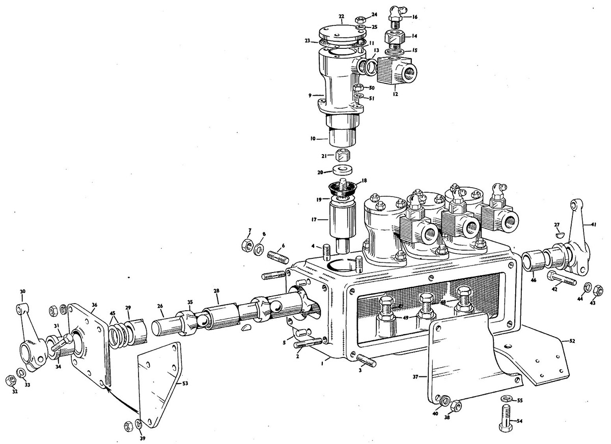
2 - The Gubbins
This is a little more complicated. Take a note of how the various brackets are arranged - it varies between engine types. The example here is a typical Leyland 680 installation, but (e.g.) the Rolls C8 uses the same throttle motor but with different brackets and the actuating arms in different positions.
Remove the hand throttle arm by undoing the pinch bolt and sliding it off. Now take off the end cover, held on by four nuts (these may also hold the bracket for the manual throttle cable clamp) and the side cover. You also need to undo the pinch bolt and remove the arm which goes to the governor, followed by its Woodruff key if fitted. (Hold the other end of the shaft in a soft-jawed vice, and tap the key out with a hammer and blunt screwdriver) The 'gubbins' will then slide out sideways, although it can be a bit fiddly getting the arms round the four adjustment screws at the top.
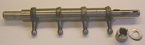
Now dismantle the gubbins (see picture) by removing the shims, arms, spacers and Woodruff keys. Take care not to lose any! Clean it all out thoroughly (white spirit or whatever), and remove any burrs left on the shaft when you removed the Woodruff keys with a fine file. Reassemble with plenty of lubrication. Look at the picture to see how it all fits together - I left the last spacer and the shims off to show which way round the shaft is (look at the positions of the Woodruff key slots which are visible). The end on the left goes into the throttle motor body first. I think!!
For those in posession of a copy of the 'DMU course notes' - the pictures of the governor / injection pump are a bit misleading. I think they are of the AEC type rather than the Leyland type although clarification would be welcome. The idling and maximum speed positions for the control lever are the opposite way around to the ones I have seen - i.e. the picture shows the lever being pulled to increase fuel, but experience suggests the opposite. This confused me when I reassembled the throttle motor a month after dismantling it, hence lesson no. 1: make a diagram when you take it to bits. The picture of the completed unit shows the arm on the left bolted up wrongly as a consequence!
3 - Refitting and Setting Up
Refit the throttle motor, minus side cover, to the engine in question, and connect air pipes, manual throttle cable, control linkage and return spring. Now adjust the four bolts inside the top of the casting to set the fuelling for each power position. This is easiest to achieve with two people, one to operate the EP valves and one to adjust the bolts in the throttle motor. It can be done by one person with three arms, however.
Set position 4 (on the left when the pistons are below) first to give full fuel (ie push the governor lever right over), and position 1 to give a little fuel.
Ideally position 1 should give a fast idle at around 600rpm. Now set positions two and three part-way between - how this is done is a matter of personal preference. I find it easiest with position 2 a little bit higher than 1, and 3 around halfway between 2 and 4. It gives reasonable control for driving in slippery conditions, and also for trundling along gently when running to steam timings!