Bristol Commercial Vehicles / Eastern Coach Works Railbus
Brakes
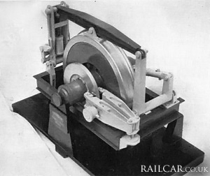
The Dunlop Monitor brake system was arranged for pneumatic/hydraulic operation of discs at each wheel. A beam carrying a Monitor shoe was pivoted on two vertical links, which in turn pivoted about their mounting brackets. An air operated cylinder was positioned in one vertical link which brought the monitor shoe into contact with the wheel rim, causing the vertical links and beam to swing in the direction of wheel rotation. An extension arm from the second vertical link energised a hydraulic double-acting master cylinder, which applied fluid under pressure to the calliper operating cylinder, forcing the friction pads into contact with the disc. Air supply to the brake operating cylinder was controlled manually by a lever on the drivers desk. Each brake was independent although all brakes were supplied together. Hydraulic fluid was supplied from two tanks, each tank having separate compartments for each brake.

The image shows a model of the Dunlop monitor brake.
Oil level in each tank was shown by a sight tube. Vents for air cylinder and calliper cylinder were piped through transparent plastic hoses to points above possible flood water level. Vent pipe extremities were fitted with filters.
Pad clearances with brakes off were automatically maintained at a constant amount - no adjustment was necessary. Pads were changed when fully worn by removal of a split pin and nut, allowing the carrier plate to be withdrawn. The calliper arms were then opened by a tool provided and the new pads secured in position. The monitor shoe was retained by a pin and a split cotter; bearing pin bushes were of the oil-less type and did not require lubrication. Hydraulic fluid levels had to be maintained within the sight level aperture. Bleeding of air was from a single point provided on the upper side of each calliper cylinder. As the wheel rims were kept clean by the rubbing of the monitor shoe on the rim, good contact for track-circuiting was made between the wheel and rail.
There was also a bus-type mechanical hand brake which operated on all four wheels and was sufficiently powerful - being assisted by the automatic servo action of the Monitor brake system - to allow the vehicle to continue to operate should the air brake fail.
Summary
Ordering Details
Description
Power Train
Brake System
Interior
Diagrams & Works Photos
Delivery
Demonstration
Operations
Final Days
Images
Neither were preserved.


