Vacuum Brakes
Operation
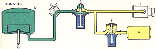
Running
The car is in motion and the exhauster is at maximum speed. The feed valve prevents the train-pipe vacuum from rising above 21 inches. To do this it does not admit air like an ordinary relief valve, but shuts down at 21 inches train-pipe vacuum, thereby isolating the exhauster from the rest of the system. The exhauster then creates up to 29 or 29 inches of vacuum in the release pipe and reservoir, giving storage capacity for subsequent brake releases. The driver's brake handle is in the off position.
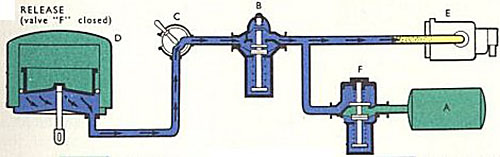
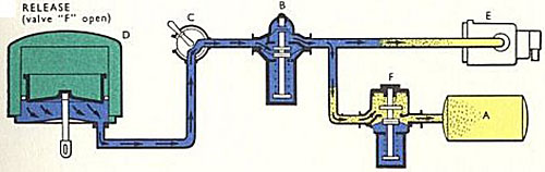
- A High-vacuum release chamber
- B Feed valve
- C Driver's brake valve
- D Vacuum brake cylinder
- E Exhauster
- F Automatic isolating valve
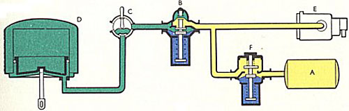
Lap
The driver's brake handle is in the lap position. The train-pipe is isolated from the feed valve and release pipe. The rain-pipe is also isolated from the atmosphere. In this position a partial brake application can be held. The drivers handle can only be removed in this position.
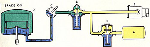
Brake On
Direct admission of air from atmosphere into the train-pipe to apply the brake. High vacuum via feed valve sealed off and thus preserved. Partial applications can be maintained by returning the handle to the lap position.
Brake Release
The driver's brake valve now links the train-pipe with the release reservoir via the feed valve. Air from below the vacuum brake piston and from the train pipe flows rapidly through the feed valve into the reservoir which is of sufficient volume to absorb all the air in the system. Immediately 21 inches is reached in the train-pipe, the feed valve closes as before. The auto-isolating valve is open.
Brake Release
The auto-isolating valve is closed and 19 inches of vacuum is maintained in the reservoir.