Charging Systems
Operation of AC8
from a BR training booklet
AC8 alternators generate alternating current which is then fed to the RUG unit. The rug unit consists of the diode assembly (silicon type) which rectifies the output.
The rug unit also consists of a second diode assembly making the alternator self excited and controlling the rotor circuit to control the output of the machine.
Replacement of AC8 Alternators and RUG rectifier / regulators
The CAV AV8 Alternator (both 50 Amp - BR Cat No. 15/58501, and 75 Amp - BR Cat No. 14/94221) and their associated RUG units were gradually phased out when more than minimum repair was required at Works.
RUG units that were considered repairable were modified at Works to help reduce maintenance and improve battery charging at engine idling.
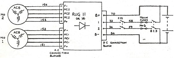
The modification consisted of fitting a new diode assembly making the alternator self-excited (similar to the AC203). This eliminated the alternator field relay (energised via the train wires 33 and 34 and the drivers key switch (see wiring diagram below). Battery charging could then take place with the engines idling without the need for the drivers key to be 'ON'.
Additionally, the main rectifying diodes (Germanium type) were replaced by the more reliable Silicon type with the removal of the two protection relays, test button and indicator lamp.
The modification was covered in Engineering Instruction MD321 issued to BREL. All modified units were designated by the suffix 'A' as follows:-
| Type | BR Cat No. | Battery Type | Voltage Setting | |
|---|---|---|---|---|
| Original Modified |
RUG 11 RUG 11A |
14/94904 15/11281 |
Lead Acid | 29.5V |
| Original Modified |
RUG 14 RUG14A |
14/98412 15/11285 |
Lead Acid | 29.5V |
| Original Modified |
RUG 15 RUG 15A |
14/94812 15/11286 |
NIFE | 31.5V |
Modified and un-modified RUG units are NOT INTERCHANGABLE
Either
a) For an unmodified unit - cables 33 and 34 to be connected up to terminals 1 and 2
Or
b) For a modified unit - cables 33 and 34 to be left disconnected and taped up.
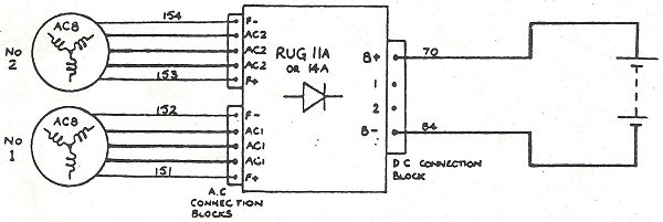
FAILURE TO DO THIS WILL DAMAGE THE ALTERNATOR FIELD DIODES AND CABLES
Modified units are identified by the removal of the protection unit (including the test button and indicator lamp).
During modification, terminals 1 & 2 (between B+ and B- in the D.C. connection block) have been rewired to allow for toilet water heating to be installed on certain power cars at works overhaul. It is therefore not possible to interchange unmodified and modified RUG units.
The following connections are correct:-
Refurbished Class 101 DMC(L) vehicles with toilet water heating
These vehicles are identified by a heater water control panel mounted next to the RUG unit.
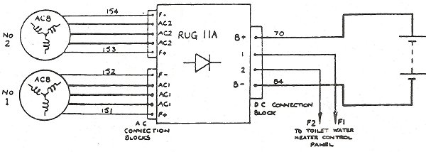
Note - only RUG 11A units must be fitted
Terminals 1 and 2 to be connected up. (A full description of toilet water
heating is in W.R. Standing Order 2/H/104).
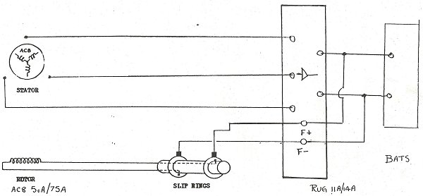
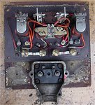
Inside a RUG 11 unit.
Dynamos (Generators)
Maintenance in preservation
Unmodified regulator settings
Modified regulator settings
Fault Finding and Maintenance
Stone's Leaflets:
A1002 - The Lamp Resistance
D1001 - Train Lighting Introduction
D1009 - Control Panel Description
E1016 - Panel, Enclosure - Open
E1018 - Panel, Totally Enclosed
P1002 - "Liliput" Regulator
P1006 - Tonum Control Panel
W1009 - Control Panel Diagrams
Alternators
Maintenance in preservation
In Introduction to Alternators
AC8 - Operation
AC8 - Maintenance & Fault Finding
AC8 - CAV Manual
AC8 - CAV Spares Parts List
AC8 - Schematic Diagram
AC14 - Schematic Diagram
AC203 - Description
AC203 - Operation
AC203 - Maintenance & Fault Finding
AC203 - Fault Finding - alternate
AC203 - CEPS 179 Overhaul Manual
CAV Rectifiers - Spare Parts
CAV460 Control Board
The Fast Fuse
FAQs on alternators


