Charging Systems
Alternators - An Introduction
from a BR training booklet
The alternator must be considered as an integral part of the complete battery charging system. It is extremely straightforward in construction, consisting basically of a field coil assembly (the rotor) which rotates inside a stationary set of generator windings (the stator).
The magnetic lines of force present around the field coil cut across the coils of the stator windings and generate an alternating current. The frequency and magnitude of this current rise as the speed of the rotor increases.
The rugged construction of the rotor permits very high rotational speeds of up to 10,000 rpm to be obtained. This in turn means that a high engine-to-alternator drive ratio can be used, resulting in a usefully high current output being generated at engine idling speeds.
Mechanical Construction
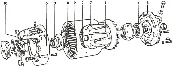
The figure below shows the construction of a typical CAV 9-diode alternator. The rotor assembly consists of the field coil, slip rings and two soft iron claws all mounted on a common shaft. The fingers of the claws (1) are interposed and form the magnetic poles, the field coil being positioned between them. Each lead from the field coil is connected to one of the two slip rings (2).
The complete rotor assembly is carried on two heavy duty ball or roller bearings (3 & 4) mounted in the slip ring and drive end shields (5 & 6). These end shields are firmly secured one to each end of the stator (7), the whole assembly forming a very rigid structure.
The three phase stator windings (8) are secured in the slotted stator laminations (9) which are themselves contained within the aluminium alloy stator.
Because the slip rings are sealed in and have to carry only light currents - in the order of 3 amperes or less - the brushes (1) can be quite small and light in weight. Consequently, brush and slip ring wear is negligible and the time periods between overhauls greatly increased.