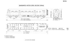
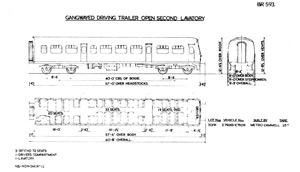
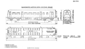
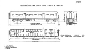
Met-Camm Lightweight 2-car DMUs
Description
The Met-Camm Lightweights differed considerably in appearance from the only other DMUs so far introduced, the Derby Lightweights, most noticeably in cab front design and window depth, Met-Camm cab windows being considerably smaller at 30" deep compared with the massive windows of the Derby units. Bodyside windows were also smaller at 34", and were mounted in thick gaskets with polished anodised aluminium frames and mounted in the body in flexible rubber mountings. This was arranged with special inside frames and india rubber seats so that the windows were easily removable and transmission of noise through the glass was minimised. The resulting neat, very modern look of the Met- Camms was enhanced by the ten degree slope of the cab front, which rose gently from just below cab window level to the roof top, forming an arch at the joint with the slightly sloping roof.
Four front marker lights were carried, one mounted centrally above the destination box which in turn was immediately above the central cab window, the other three being displayed in a row across the lower cab front, one above each buffer with the third placed between. Multiple-unit control receptacles were mounted at waist height below each outer cab window, and provision was made to stow jumper cables in the driving cabs when not in use.
Roof vents were of the flat profile 'Airvac' type, similar to those that would be fitted the Cravens, BRCW and Park Royal built units, as opposed to the more usual 'Shell' vents of the Derby design cars and coaching stock. These were placed diagonally in groups of three and spaced at intervals along the length of the rooftops.
Standard buffers & drawgear were fitted. The buffers were self contained with india-rubber springs. They were of 18" diameter and mounted on 4" steel stubs, between were the vacuum pipes, with one train pipe and one high vacuum pipe placed on either side of the coupling hook which was provided with a three link screw. Below the buffer beam twin air horns protruded from a deep cowling which covered the leading edge of the front bogie, resulting in a somewhat streamlined appearance to the front of these units, though a number of units ran minus the cowling in the last years of their operation. This feature was omitted from the later all steel units when multiple unit jumpers were moved below the buffer beam.
Other features peculiar to the Met-Camms were the lack of a cantrail rain strip or gutter making the seam between bodyside and roof barely detectable. Instead short rain strips were provided over each bodyside door. Rear facing brake van windows were fitted which were only 9" wide though about 30" In depth, looking very reminiscent of medieval arrow slits, placed at the extreme rear corners of the DMBS vehicles with exhaust stacks and Midland style "scissor" corridor connection.
Being of the same bodyside profile, the steel passenger and drivers doors were interchangeable with the standard coaching stock of the time (Mark Is) although it is doubtful this ever happenend in practice.
The guard's door was incorporated into one half of the double loading doors at the rear of the DMBS vehicles, the guard's portion contained a droplight window and opened into the van, and looking from outside, being positioned to the right of the plain door which opened outward, this feature being the same on both sides of the vehicle.
Structure
The side framings, mainly of steel pressings, extended as a complete unit from below the underframe to well into the roof portion and this provided an excellent structure to take care of all superimposed loads. The side panels, also of steel, were spot welded to the structure. The framing members of the central portion of the roof were aluminium alloy, and the outer sheets were of aluminium with aluminium ventilators fixed by rivets. The body ends were steel. As protection against condensation and noise a layer of asbestos was sprayed on the inside of all the body outer panelling.
Underframe members were made up of rolled steel sections and fabricated units. The end framing, including headstocks and bolsters, was a completely fabricated unit and other sections were dealt with in a similar manner. BTC specifications meant that the design had to be suitable for a 200% overload. To test this, the first body shell was loaded with 26.5 tons of weight which represented full equipment and three times the normal seated load. This caused no permanent set, neither did further tests with completed cars.
All units were jig built to ensure interchangeability, and care was taken in the disposition of various body members, so that the required variations in the layouts of the different types of cars could be produced from the same jigs.
Bogies & Brakes
Bogie frames were of fabricated sub-assemblies and rolled sections and plates all riveted together. The bolsters were of the swing type but anti-sway hydraulic dampers were fitted in the bogies to control and minimise lateral motion of the cars to provide smooth riding at all speeds. The springing consisted of laminated side springs with india-rubber auxiliaries and nests of coil springs in the bolsters. The axleboxes were of the taper-roller bearing type fitted with manganese steel liners. A mileage counter was mounted on the axlebox of the leading axle of each power car. The brake rigging was arranged for combined screw and pin adjustment, and standard brake heads with renewable shoes were fitted.
The Gresham & Craven two-pipe quick release vacuum brake system was used. The brakes on the driving trailers were operated by 18-inch standard vacuum brake cylinders mounted on the underframe. The power car bogies, as well as accomodating the final drive on the inner axle, had a standard 22-inch cylinder mounted on the outer end, leaving more underframe space for power equipment.
Power Equipment
British United Traction (BUT) supplied the power and control equipment, which was generally similar to that in use on the Derby Lightweights, although some improvements were incorporated following running experience. Two AEC 220 150hp engines were fitted each driving, through a hydraulic coupling and a short cardan shaft with flywheel, a four-speed Wilson epicyclic gearbox. From this a main cardan shaft connected to the reversing final drive. The radiator cooling fan was engine driven via a bevel drive. Each power car had an 80-gallon fuel tank for each engine, and one had extra capacity to feed the heater. Mounted on each engine was an air compressor of 10 cu ft per min. capacity at 1,000rpm to supply compressed air for the control system, windscreen wipers and horns. Two rotary exhausters were fitted to the power cars, driven by v-belts from pulleys mounted on the input end of the gearboxes, and each had its own oil-air separator. Electro-pneumatic controls operated the engines, gearboxes and forward and reverse gears in the final drive.
The multiple control system was designated "yellow diamond", and the cars were compatable with the Derby Lightweights (except the West Riding cars). A Stones generator of 150amp output was provided on the power car driven by v-belts from a pulley mounted on the output end of one of the gearboxes. A Nife battery of 400 amp/hr capacity was carried in two steel boxes on the underframe. The generator on the trailers were of similar type but of 60 amp output while the Nife battery was of 220 amp/hr capacity. A Graviner type engine fire protection system was fitted, and there was also hand held fire extinguishers in the drivers and guards compartments.
Suppliers
Some of the other main suppliers that supplied components for the vehicles:
- Wheels and axles by Taylor Bros & Co Ltd.
- Roller bearing axleboxes by British Timken Ltd.
- Steel springs by the English Steel Corp Ltd.
- India rubber springs by George H Spencer Moulton & Co Ltd.
- Vacuum brake gear also supplied by the Vacuum Brake Co Ltd.
- Speedometer, mileage counters, generators & passenger lighting fittings. by J. Stone & Co (Deptford) Ltd.
- Heaters by S. Smith & Sons (England) Ltd.
- Sprayed asbestos by JW Roberts Ltd.
- Windows by Beckett Laycock & Watkinson Ltd.
- Plastic panelling by Insulation Equipments Ltd and Warerite Ltd.
- First class seats by Lace Web Spring Co Ltd.
- Third class seat tubular frames by Accles & Pollock Ltd.
- Leather cloth by Ioco Ltd
- Alkaline batteries by Nife Batteries Ltd.
Cab
The layout of the drivers compartment, which was finished in maroon and black to minimise glare and reflection, was given special attention. A spacious cab was provided, and all controls, instruments, gauges and so on arranged conviently for the driver. The desk was the full width of the cab, and also incorporated the handbrake. Removeable panels provided maximum accessibility to all equipment. An air operated windscreen wiper was fitted to the drivers side only, as was a sun blind. The drivers adjustable seat was upholstered in hide.
The throttle control handle also incorporated the "deadman" control, if the driver released the handle the engines would be returned to idling and after a 5 second delay the brakes would apply.
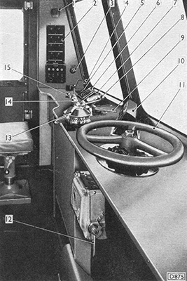
In the first of two different diagrams of cab controls, from a BUT maintenance manual, the numbers correspond to:-
- Guard's Signal Buzzer
- Control Panel
- Destination Indicator Light Switch
- Combined Throttle Lever and "Deadman's Handle"
- Engine Speed Indicator Switch
- Speedomoter
- Engine Speed Indicator
- Change-Speed Selector Lever
- Forward and Reverse Lever
- Air Pressure and Duplex Vacuum Gauges
- Handbrake Wheel
- Train Switch
- Vacuum Brake Lever
- Horn Switch
- Windscreen Wiper Valve
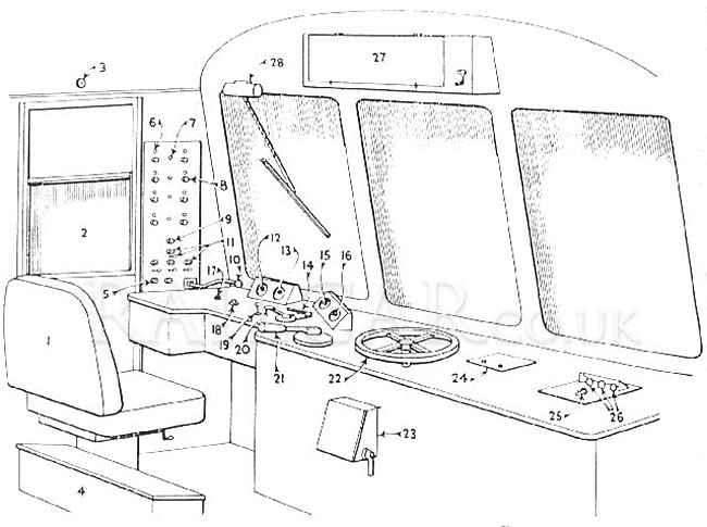
1 Adjustable driving seat
2 Cab door with droplight
3 Switch for cab light
4 Box for spare cables
5 Deadman's indicator light
6 Engine tell-tale lights
7 Air pressure tell-tale lights
8 Engine started buttons
9 Engine stop button
10 Combined throttle and deadman's control
11 Marker light switches
12 Gear change indicator
13 Speedometer
14 Reversing and master key
15 Air pressure gauge
16 Duplex vacuum gauge
17 Signal bell to guard
18 Windscreen wiper valve
19 Two-note horn valve
20 Four speed gear lever
21 Vacuum brake
22 Parking brake
23 Control switch
24 Passenger lighting
25 Heating control switch
26 Heater tell-tale lights
27 Destination indicator
28 Windscreen wiper
Interiors
The whole of the sides from near the floor to above the parcels racks including all cross partitions, were covered with plastic panels in Stardust Buff 95 pattern secured to hardboard, which provided for ease of maintenance. Parcel racks were fitted to the whole length of the bodysides, with aluminium brackets and tubes, with netting of suitable shades. All mouldings, inside window frames and edgings were of polished aluminium, and ceiling panels were in off-white.
Lighting in passenger saloons was by 60 watt 24 volt lamps in semi-enclosed circular fittings.
Heating was by an oil burning heater fitted below the floor of each car with the necessary oil tank and filter. The warm air was fed through insulated ducting arranged immediately above the floor on both sides of the saloon and secured to the bodysides with suitably designed apertures below a number of the seats. Control was by a special switch mounted on the drivers desk. The system was fully automatic (thermostatically controlled) and could also circulate unheated air.
The internal layout of the cars varied between Eastern and London Midland vehicle, although externally they were identical. Only the trailers of the LMR sets were built with first class, and the ER sets had smaller guards vans, giving an extra row of 2+2 seating next to the rear vestibule.
The 2+3 seating in the middle saloon was on opposite sides on the DMBS from the trailers. On the seats the metal tubular seat framing was also finished in colours to match the moquette, which differed between the two Regions.
Eastern Region vehicles


Inside a DMBS and DTSL. The moquette was maroon with tan vinyl.
London Midland Region vehicles


The moquette was green with light green vinyl. First class was midnight blue in first class.
Adding First Class
Some of the Eastern Region driving trailers had their front saloon converted to first class. The earliest image of the conversion seem to be from the green whisker with revised lining era. What this actually involved, other than adding the first class totem transfers to the windows, is unclear. No images show any signs of curtains, and the seating is the same airline arrangement and placement (four rows facing the cab) with the seats in the same style. The data panels note 16 first class seats, so possibly the only change being the three triples reduced to doubles.
Vehicles converted that have been identified include 79269, 79272, 79275, 79286. 79291 had a vehicle code of 'DTCL' on the inner end but there are no signs of first class signs in the windows. Also an unidentified vehicle.
Summary
Description
Works Photographs
Numbering & Driving Inst.
Liveries
Operations
Non-Passenger Use
Images
No vehicles were preserved.


