
Class 104 BRC&W 2, 3 & 4-car DMUs
Description
In common with other first generation designs, the bodies and underframes were built as an integral structure — the complete body and underframe being capable of carrying all the superimposed loads normally encountered in service, and with a 200% overload.
Underframes and Bogies
A BR booklet listing all the parts of a bogie along with part and drawing numbers.
Download PDF (10mb)
The underframes were a conventional design of mild steel rolled sections and plates, with members spaced to accommodate the power and transmission equipment, and fabricated by electric welding. Standard BR drawgear and light alloy Oleo hydraulic self-contained buffers were fitted - although some were fitted with spring buffers mounted on adapter brackets until receiving the one piece Oleo's during overhaul in the late 1970s.
The standard BR DMU design swing bolster bogies were used, fitted with Timken roller-bearing axleboxes and lateral control bolster dampers.
Body Construction
The main body pillars were formed from 16 s.w.g. thick mild steel pressed top-hat sections, the flanges located against the outer skin to form hollow box sections. These were connected by light and waist rails together with intermediate 16 s.w.g plate of both angle and "z" section, and a 1/8 inch plate cantrail. The main carlines were of similar section and thickness as the pillars, and were tied together by purlins of shallower top-hat section.
The body side, end and roof panelling was 16 s.w.g. steel, and these were stitch welded to the body framing in cast iron jigs to minimise distortion and buckling of panels. All joints between adjacent body side and end panels were welded and ground smooth after assembly to provide a completely flat exterior.
For heat and noise insulation cars were sprayed with asbestos, 1/4 inch thick on the inside of the side, end and roof sheeting, and 3/8 inch thick on the underside of the aluminium dovetail floor sheets. These were covered with 1 3/16 inch thick cork, to give better protection against noise, onto which the linoleum was laid.
Cab Design
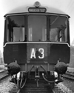
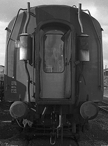
When new the cabs fronts differed physically only in the marker lights that they carried.
The early deliveries - DMBSs M50420-3 & 50428-43 and DMCs 50424-7 & 50480-95 (all from LMR 3-car sets) - were built with one marker lamp, moulded into the glass-fibre cab roof dome above the destination indicator.
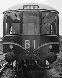
The rest were built with two lamps, one above either buffer, the roof one was ommited.
There were two anomolies to the above, and the reason why remains a mystery for each. LMR DMC 50529, numerically one of the last vehicles, should only have had the two lower lamps but it also had a roof dome with a marker light. For many years it was the only vehicle with three marker lamps. It is unsure whether it was built with this or it was a replacement, it had this since at least 1961.
LMR DMBS 50429 should have only had the top lamp but only had the two bottom lamps. The earliest photograph found where the vehicle is identifiable is from circa 1969 (in the 1970 DMU ABC), so if this was not built like this and the changes were done in an accident repair it was before this date.
In later years starting circa 1981 the roof lamp vehicles had the lower ones added. In this era the marker lights were allowed to be used as tail lights, and adding the lower lamps avoided the need to use oil burning tail lamps. Often the roof ones were often left in place unused. These 'new' fittings were normally in a slighlty different position from the original placement being centered under the grille rather than offset to the left.
Van Doors
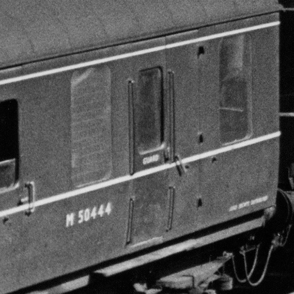
The early DMBSs — those for the LMR three-car sets (50420-3 and 50428-79) — had the inward opening door on the left hand side of the number one (drivers) side of the vehicle.
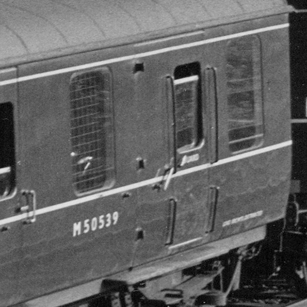
The later brake vehicles — the LMR two-car sets and all ER sets (including the TBSs) — had a right hand inward opening door on the number one side of the vehicle.
All brake vehicles had the inward opening door on the left hand side of the number two side of the vehicle.
Why the change on the number one side? We can only guess the reason, but as the van storage space was on the left of the double doors, the inward opening door would be an obstacle when trying to load / unload, and the door swinging inwards could also hit and damage items stored inside.
Inner Ends / Gangways
This image shows the inner end of a power car, this being DMCL 50549.
The cylinders on the exhaust pipes are silencers, the type used would vary over the years. Being a vehicle with a lavatory, there is a water filler pipe on each side to fill a water tank fitted above the toilet ceiling.
The gangway is a standard LMS design scissors type.
The brake van end of DMBS and TBS vehicles, and the non-toilet (vestibule) end of TS and TC vehicles had two large windows, the same size as the cab windows, one either side of the gangway.
Power Train
British United Traction (BUT) supplied their standard engine and transmission equipment. A power car had two Leyland 680 engines, each driving a final drive on the inner axle of the nearest axle via a freewheel, a Self Changing Gears R14 four speed epicyclic gearbox, and cardan shafts. An air compressor was mounted on each engine to supply air for the electro-pneumatic controls. Radiators, mounted on the side of the frames were cooled by fans driven by a right angle drive on the engine. Each exhaust system had two silencers to cut down on noise.
An empty three car set (86 tons tare) produced approx 7.0 horsepower per ton, fully laden it would be about 6.0hp per ton.
J Stone & Co (Deptford) Ltd provided the lighting equipment, with 60W 24V lamps in the saloons powered by 150 amp Tonum generators. Standard BR A2 type lead acid batteries were used which had a capacity of 440 amp/hour. Destination and route indicator boxes could also be illuminated.
Brakes
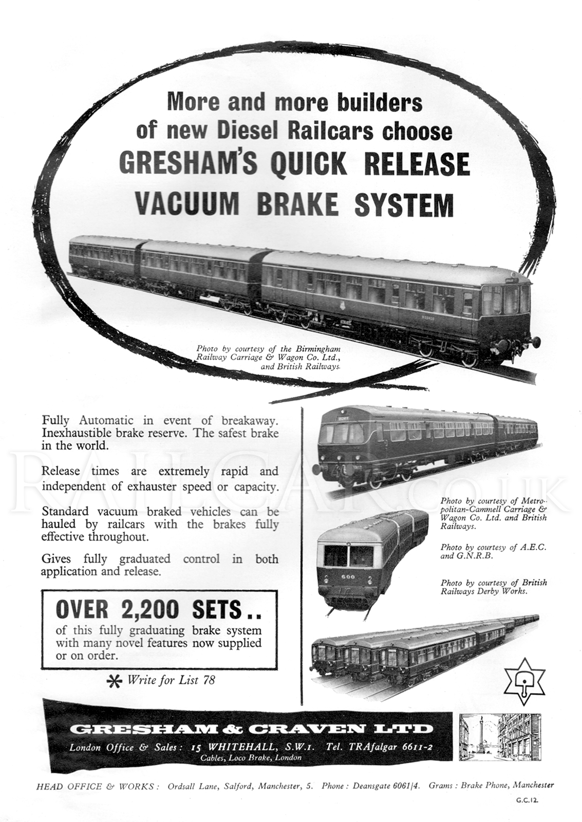
Brakes were the standard Gresham & Craven quick release vacuum type, with two Clayton exhausters also driven from the transmission by v-belts. There were emergency brake valves in the guards van, and in each cab, the cabs also contained handbrakes. The TBS vehicles had a vertically mounted handbrake wheel by the corridor connection door but these was later removed.
Some Gresham & Craven adverts of the period feature a three-car BRC&W set (which seems to be missing the route indicator on the cab front).
22 inch vacuum cylinders were carried in the power car bogies, although they were later changed to the 21" rolling ring type. Trailer cars had 18" cylinders and one bogie also carried a dynamo. On the power cars the dynamos were driven by V-belts from the transmission.
A BR booklet listing all the parts of the brakework along with part and drawing numbers.
Download PDF (11mb)