
Derby Lightweight (Red Triangle) 2-car DMUs
Construction - Body

The bodyside frames were made up from body pillars which had been bent to the correct radius during manufacture. The framing members were machined as required and inter-sections jig-drilled before being offered up to the bodyside assembly fixtures. The cross section of the extrusions used were designed so that with the minimum of machining they would interlock on assembly and present lapped surfaces ready for riveting.
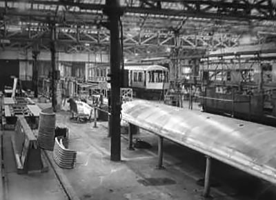
In the first image a bodyside frame can be seen on the left in the assembly jig. The black sections keep the window apertures at the correct distances. To the right is a stand containing the pre-bent bodyside pillars, and to the right again a vehicle end is under construction. In the foreground there is a bodyside panel on the table and another on the stand to the right. To the right again is the jig for assembling these body panels (this is shown in the second image). Vehicles can be seen in various states of completion. On the left, framework is taking shape on top of an underframe (an end panel and side panel visible), in the centre a vehicle with a roof is awaiting a cab dome, and to the right a roof is being lowered onto another. The triangle cut into the inner body panel shows that this is a West Riding DMC.
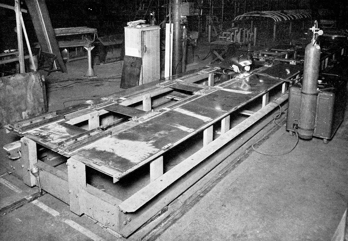
The bodyside panelling was 10 s.w.g. sheet, cut so that all joints were horizontal. This meant that the sections above and below windows were unbroken between doorways, requiring panels up to 20 feet long. To provide a flush finish for improved appearance, the sheets for the bodyside panelling were Argon arc welded together as seen in second image, where the panels are clamped face down. To acheive maximum strength, on the jig under where each butt joint would be was a copper strip which had a 1/8 in. x 1/16 in. groove. The weld would penetrate the joint and fill up this groove, providing a small fillet on the outer face of the panels, and a relatively large fillet was allowed to form on top (the inner face). To obtain a clean start and end to the weld, a small panel offcut was positioned at each side. This avoided any under-cutting of the panel edge during welding and the offcuts were easily removed at a later stage. Also note in the top right of the image the framework for a roof section sitting on its assembly jig.

Once the completely welded panels were removed from the welding jig the 1/8 in. x 1/16 in. fillets (on the outer face) were ground off, leaving a smooth finish. The larger fillets on the inside face were only removed where they would be located against framework when assembled. In the first image on this page the sheet on the table still has the fillets, the sheet on the stand does not. Next, the panels were drilled to templates and placed on the bodyside framework, still on the assembly jig, as seen in the next image. They were lined up using the door and window opening reference jigs, then the panels used as a template to drill through the framework. This ensured the holes lined up and were the correct size for better fitting rivets. These were also light alloy, cold formed and countersunk, the heads were left 1/32 inch proud.
To obtain a flush finish to these heads a special tool needed to be designed which was light and portable would remove the excess without damaging the surrounding panel. After some experimentation it was found that controlled vertical milling produced the best results. The resulting tool consisted of a tungsten carbide end mill rotating within a guide or fence and mounted in an Armstrong Whitworth head secured to and driven by a Desoutter compressed air motor. A pair of adjustable guide rollers mounted on ball bearings were fixed to the head to assist in propelling the tool over flat and curved panel surfaces. Compressed air was admitted to the motor by a spring loaded push button, which also allowed a small amount of air to be by-passed through a tube and blown across the cutters to remove swarf. Micrometer adjustment was provided to compensate for wear and regrinding the cutting edges of the end mill. Under actual working conditions about 0.015 in of the rivet head projected above the panel after riveting, and this was milled away to leave about 0.001 in for final dressing of by means of a small air driven cone-shaped mounted stone. The tool weighed about 3¾ lb. and was air operated at a pressure of 90 lb. per sq. in, rotating at approximately 4,000rpm.
The assembly of the roof followed a similar method to the bodysides. The carlines, purlins and cantrail extrusions were machined to length and jig-drilled before assembly. The cantrail was placed in the assembly fixture followed by the inner carlines, purlines and outer carlines, all located using the previously jig-drilled holes. Snap head rivets were used to combine the parts. Next pre-assembled conduit piping and junctions were threaded through the framework which would carry the lighting wiring. The panelling was 14 s.w.g. sheet with the roof vent apertures cut out, jig-drilled and rolled to form the overlapping lip and general roof curvature. They were clamped securely to the framing and used as a template for drilling the holes for the snap head rivets. The image shows a completed roof sitting on the assembly fixture, with a stack of inner and outer carlines on the floor to the left ready for the next assembly.
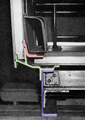
With the underframe, side, end and roof parts ready they could now be brought together. The bodyside assemblies were lifted into position as complete units using specially designed lifting beams. On the bottom of the bodyside assembly the outrigger (green in the first sectioned image) located against the top flange and outer face of the solebar (purple) - the floor panels and other interior parts shown in the image weren't in place at this stage. The top of the bodyside assembly was held in position at this stage by the triangular reference fixtures (seen in the last image on the underframe page) which were located along the centre floor support while the sides were fully riveted to the underframe. The end assemblies were then added, before the vehicle was moved to the roofing position, and again propped. The roof was then lifted from its assembly fixture by a lifting beam which had arms that passed through the roof vent apertures. The cantrail was in two halves, the top half (purple) being part of the roof and the lower half (red) being part of the bodyside frame.
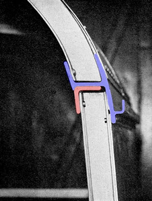
Bevelled edges on the two halves ensured positive location on assembly. Because of accessibility issues the roof was secured in the vertical plane with cadmium-plated high-tensile steel bolts and Simmond Pinnacle nuts. The lower flange of the roof cantrail was also snap head riveted to the bodyside under the roof gutter.
The roof purlins were then extended and secured to the end framing by an angle section rolled to the shape of the interior of the roof dome, the dome being riveted to the end framing, roof and bodyside.
On early vehicles the end roof domes (a.k.a. end canopies) were fabricated from nine small sections of 14 s.w.g. light alloy sheet, each requiring to be individually rolled and beaten into shape by sheet-metal workers before being welded together to form a complete dome. This proved too time consuming, and evolving technology soon allowed the domes to be formed from glass fibre.
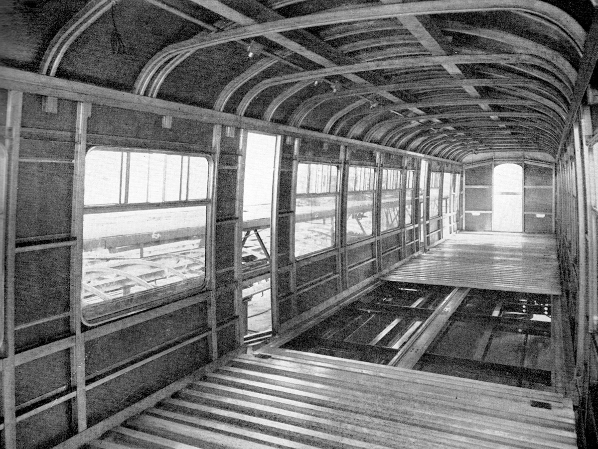
The final part of constructing the bodyshell was fitting the floor. This was made from extruded light alloy in an extended H section (Item 15). They were riveted to the underframe floor bearers and outriggers with Chobert rivets, which were magazine loaded and mandril operated - designed for one-man operation in positions where the actions of a holder-up would be restricted. The floor sections ran across the vehicles, unlike some other designs which ran longitudinally to increase end to end strength. The bodyside framing was securely attached to the floor members by an angle section (red in the first sectioned image) positioned along the base of the bodyside and over the ends of the floor members, fully riveted to both. The next image shows a floor partially fitted. Note the small rectangular holes just inside the doorways. This was for heater ducting to pass underneath the doorways, otherwise the ducting ran inside the vehicle as seen in the sectioned image above.

There some notable differences between this and the next image which has a completed floor. The first one is undated but seems to be a later vehicle in the production run as it already has glazed window units fitted, at some point the assembly method was changed with these being inserted before the sides were united with the underframe. Also note at cantrail level the additional short vertical 'stubs' of framework, these were for the luggage rack to fix onto, not on the second earlier image.

It was taken on the transverser at Derby in early 1954, as was the next image, showing a completed bodyshell. On the bufferbeam is written "30084/2 VEH. No.3" - so it's clearly a West Riding DMBS. The bogies are not DMU bogies, they are just fitted to move the vehicle around between shops.
The next two images are further assembly scenes from early 1954. In the foreground of the first is the underframe assembly fixture with many underframe parts ready to be brought together. Facing it, is a complete looking underframe, and behind it, seen in the second image is yet another, this one having the vacuum brake piping fitted. In both images many West Riding vehicles can be seen in various stages of construction.


The final image, also early 1954, was taken during the interior fitting-out. The frames for the partitions are in place, the floor has been fitted along with plates to attach the seats. There is also signs that the wiring is well advanced. Window frames are fitted to the left side only, and the first panelling that seems to fitted is the cab ceiling. The triangle cutout on the cab end panelling shows that this is a West Riding vehicle.