Derby Lightweight (Red Triangle) 2-car DMUs
Description
Drive Train
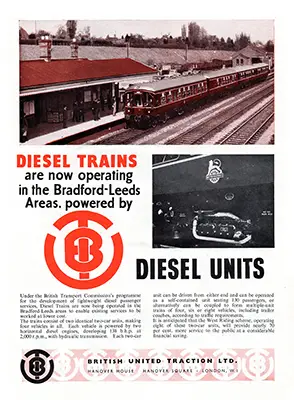
Two Leyland L600/229 engines were fitted to each car. Some sources, such as the British United Traction advert below, and the driver instructions show these were rated at 138hp, other sources such as the diagrams show them at just 125hp. Each powered the inner axle of the nearest bogie. Multiple working provision was made for eight power cars. Start and stop controls were provided for each individual engine. The fuel tanks held 232 gallons.

These vehicles had Lysholm Smith torque converters, which were of a unit construction with the engines. They were made up of: a double acting clutch for connecting the engine to either the pump wheel of the torque convertor drive, or direct to the output shaft; the hydraulic system of the torque convertor; and the freewheels which were incorporated into both the convertor and direct drive to allow the car to over-run the engine. While at one time this set up had been common in road vehicles, by 1953 it had been superseded by the pre-selector system, meaning the DMU's transmission system was obsolete by the time they were built. Derby most likely used this transmission because of it's own previous experience with the 1938 LMS unit.
The clutch was the double-acting type with a neutral position, operated by a single toggle mechanism, which in turn was operated by a double acting air cylinder. The hydraulic portion of the torque convertor consisted of a centrifugal pump in a single casing with a three stage hydraulic turbine which gave a maximum torque multiplication of five to one. The free wheels were of the roller type, built into housings secured to the rear of the convertor housing.
Manual change of the controls was neccessary when the driver wished to isolate the torque converter and change to direct mechanical drive, unlike 50000 which changed automatically.
The final drives were of the double reduction type, with an overall reduction of 3.58 to 1, and were developed jointly by Leyland Motors Ltd and Walker Bros. (Wigan) Ltd. These two firms also developed the controls together. All were electo-pnuematically operated from two 24-volt batteries, and consisted of electrical switches which operated magnetic valves throughout the train. The driver had an engine speed control, a clutch control and a direction control. The engine speed was controlled by small air cylinders, with four being built into a unit mounted next to the butterfly valve on the manifold. This provided four engine speeds plus idling.
The clutch had four positions, handle off, neutral, converter drive and direct drive. It was only possible to start the engine or change direction in the neutral position. The clutch was controlled by an air cylinder built into the torque converter, with air being admitted through two magnetic valves adjacent to each converter. To avoid the speed of the train exceeding the engine speed two freewheels were incorporated into the torque converters, one for the converter drive and one for the direct drive. Forward and reverse direction control was obtained by air actuated pistons which operated the forward and reverse sliding pinions. The sets were geared for a normal maximum speed of 62mph.
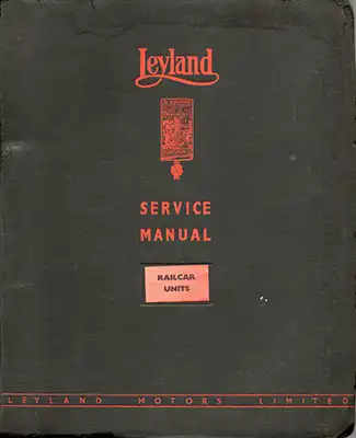
Service Manual
The Leyland Service Manual for the vehicles gives more information on the technical aspects. PDF download (44mb).
The cover was 8 1/2" x 10 3/8", the pages inside were 8" x 10". All the technical sections were single sided, all but two sections had the pages numbered only in odd numbers.
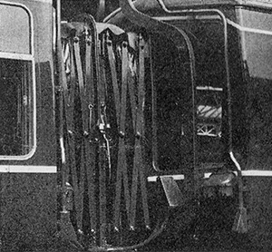
Cab Front / Gangway Ends
This first batch could be distinguished from later builds by the lack of a centre marker light and the triangular jumper lead box. The three front windows did not have any horizontal dividers, which were fitted to builds after the West Cumberland batch. Laycock - Sprague air operated windscreen wipers were fitted to the drivers side only.
LMS scissors type gangways connected the vehicles. Exhaust pipes were rectangular rather than tubular. All vehicles had filler pipes on the gangway end for the coolant tanks mounted in the ceiling space in the vestibules, and also for the toilet on the composite vehicle.
Driver Controls
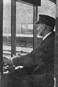
British United Traction supplied the control system, as they went on to do for many of the first generation DMUs. Certain controls were unique to this build, such as the engine start/stop panel (the silver panel on the wall) and the throttle / transmission controls, but they can be seen in railcar vehicles in Ireland which BUT had also been heavily involved with.
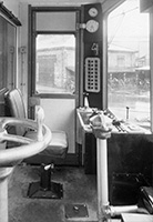
The driver's desk was not full width, the brake controls being free standing to the right of the desk - this was one of the few controls in this build which stayed consistant throughout all first generation DMUs. The duplex vacuum gauge and air pressure gauge above it would remain in this position for the first few builds but later builds had them moved to a position at desk level.
The button on the floor is presumed to be for the sanders.
A dead mans device was built into the throttle, if this handle was released for more than 5 seconds all engines returned to idling, the clutches returned to neutral (which prevented the engine from stalling) and the brakes were automatically applied.
Interior
The drivers cab was separated from the passenger accommodation by partitions with the top half in glass allowing passengers a forward/rear view.

Tubular steel framed seats were trimmed with maroon moquette in the third class and blue uncut in the first. The pattern in both classes was set out in narrow vertical lines. Vynide was used on head rolls and seat borders. First class saloons (pictured) was in a 2 + 2 arrangement with 16 seats, three rows facing the cab, one row facing away. Third class was in a 2+3 arrangement, all seats faced the cab except one sideways seat in the rear saloon of the composite vehicle. All passenger windows had pull down blinds.
Interior panelling was Vynide cloth covered flameproof hardboard, in various colour schemes. Luggage racks were provided along the complete length, formed from light alloy tubes of square section. There was a toilet in the composite vehicle, decorated with primrose plastic panels and rubber floor tiles.


