Derby Lightweight (Red Triangle) 2-car DMUs
Construction - Underframe
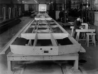
The underframe was assembled mainly from standard extruded aluminium channel, angle and T-sections. The rivet holes were drilled 1/16th in. undersize before bringing the parts together, then opened up once in place. This helped with alignment and better fitting rivets. All holes were slightly countersunk to eliminate the possibility of stress areas under the rivet heads.
The first image shows an underframe in the early stages of construction. Many of the parts have been arranged in place ready to be riveted together. Note that in the first section behind the headstock - at this stage the inner longitudinal members run parallel. All images on this page are dated 1953 and so all are believed to be for the West Riding sets.
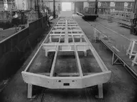
This underframe has had most of the pieces riveted together. However the parallel section immediately behind the headstock only has a few nuts and bolts holding the beams in place. This could suggest that either the proper parts were not yet ready, or that the design was actually changed at this early stage when it was thought that more strength was needed here.
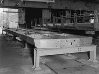
The next step in the process was to lift the underframe onto a set of bogies. This image shows a set of chains attached ready to lift the assembly. It has many more holes drilled in the transverse sections that will allow items to pass through later.
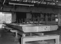
Movement in progress. Although the underframe appears similar in these first four images, looking at the surroundings and the stands the underframes are sitting on, there are three distinct assembly areas. Also, I've displayed the images in the order of construction and not in the order they were taken.
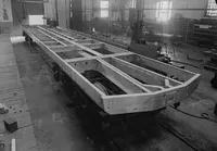
Now sitting on bogies. The temporary parallel longitudinal beams in the first section have now been replaced and properly riveted, and it looks a lot more substantial. As the vehicles were of integral construction, the underframe on its own was not able to support its own weight over long periods and props can be noted in the mid-section. These were set to give it 3/8 in. positive camber.
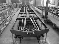
The final image shows an underframe that appears completion. It now has two vacuum pipes fitted (train and release). Noted in the nearest corners are additional props. It is also painted. Bodyside jigs can be seen on the left, it contains the frames for a front and rear section. The mid-section (each section being divided by the passenger doors) is actually fitted to the underframe, if you look closely it's the centre section on the right. The triangle frame in the centre holds this in the right position until the other pieces are in place.


