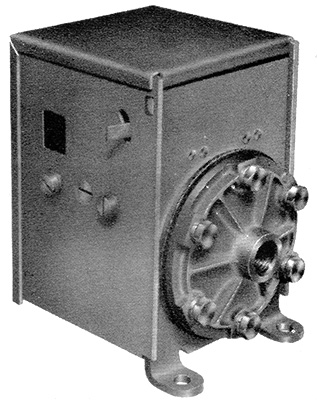
One was provided per final drive. They could be located out of view in the cab or on the underframe. They were painted red — the round alloy air connection (on the right of the image) was unpainted.
From the BUT 50000 Series Service Manual:
The air pressure switch indicates electrically, by means of a light on the driver's control panel that a minimum safe air pressure is available.
The indicator light will not be switched on until the final drive is properly engages and the correct air pressure is obtained.
The switch is a totally enclosed unit with a small trigger, which is integral with the switch, projecting from the side of the casing. This trigger can be operated manually, if required, to test the circuit between the switch and lights.

Schematic showing the electrical connections, as shown in the BUT 50000 series manual.
Both were connected to the "Train -" circuit, wire 34. When sufficient air pressure was available the "Train -" connected to wires 113 (forward) and 114 (reverse) which went to the "Direction Indication Switch" on the final drive.
Introduction
Throttle Controller
Gear Controller
Engine Control Relay Panel
EP Control Relay Panel
Starter Motor Isolation Relay
Relay Operated Switch Panel
Electro-Pneumatic Valves
Air Pressure Switches
Water Level Switch
Engine Shutdown Solenoid
Oil Pressure Switch
Battery Isolating Switch
Engine Isolating Switch
Direction Switch
Engine Local Control Box
Engine Plug and Socket