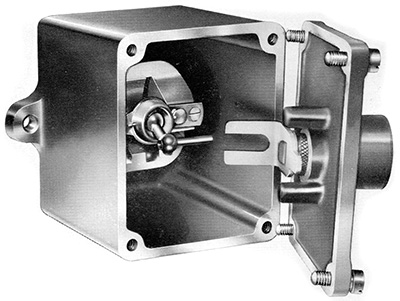
One was provided per engine located on the underframe. The outside was normally painted red.
From the BUT 50000 Series Service Manual:
This switch is one of the tumbler type and is operated by a standard railway carriage key when for any reason it becomes necessary to isolate and engine.
Each engine is provided with a switch, which is waterproofed and requires no maintenance.

This shows the connections to the switch, taken from the BUT 50000 Series Service Manual.
It is a simple on/off switch in the complicated path of connections that leads to the operation of the starter for the associated engine, and is located between the "Engine Control Relay Panel" and the "Fire Alarm Control Panel".
The two wires for number one engine (illustrated) are 62 and 101, for the number two engine they are 63 and 104.
Introduction
Throttle Controller
Gear Controller
Engine Control Relay Panel
EP Control Relay Panel
Starter Motor Isolation Relay
Relay Operated Switch Panel
Electro-Pneumatic Valves
Air Pressure Switches
Water Level Switch
Engine Shutdown Solenoid
Oil Pressure Switch
Battery Isolating Switch
Engine Isolating Switch
Direction Switch
Engine Local Control Box
Engine Plug and Socket