From the BUT 50000 Series Service Manual:
The water level switch is mounted on the header tank and is attached to a float; when the water in the tank reaches a low level, this float magnetically operates the switch, thereby actuating the engine shut-down solenoid and stopping the engine.
Incorporated in the float assembly is a permanent magnet which is opposed by a similar magnet in the switch assembly.
The adjacent poles of the two magnets repel one another, and by this method the switch contacts are made to change over with a snap action.

Schematic showing the electrical connections, as shown in the BUT 50000 series manual.
It was a simple on/off switch, connecting the "Local -", circuit 52, to 52W which went to one of the "Oil Pressure Switches" via the "Engine Plug and Socket".
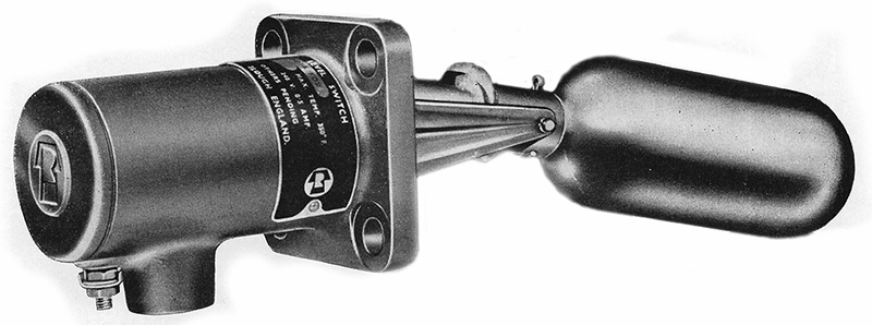
A typical water-level switch was the 'Mobrey Switch', this example was supplied by Ronald Trist & Co. Ltd.:

Introduction
Throttle Controller
Gear Controller
Engine Control Relay Panel
EP Control Relay Panel
Starter Motor Isolation Relay
Relay Operated Switch Panel
Electro-Pneumatic Valves
Air Pressure Switches
Water Level Switch
Engine Shutdown Solenoid
Oil Pressure Switch
Battery Isolating Switch
Engine Isolating Switch
Direction Switch
Engine Local Control Box
Engine Plug and Socket