
Building a DMU
Both Derby and Swindon photographed their first DMU builds extensively (later builds less so).
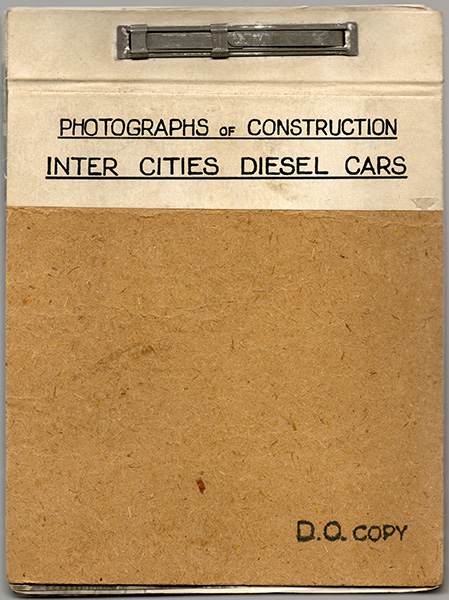
Swindon produced an internal booklet "Photographs of Construction, Inter Cities Diesel Cars", containing just over 100 images of the construction of the 79xxx Inter-City vehicles; although many of these are actually of completed vehicles. It is featured here courtesy of the Swindon Diesel Preservation Society. The images are presented in the same sequence as the booklet, which does not represent the date order of the prints.
Some of the Derby construction images can be found here: underframe and body.
Part One: Bogies
The first eight images in the booklet show the bogies (all taken on the 24th November 1955). The captions are brief, this description from a press release at the time vehicles entered service may give a better insight:
"The Bogies, which have a wheelbase of 8 ft. 6 in., are of riveted construction, using rolled steel sections and fabricated sub-assemblies. Rolled steel disc wheels, 36 in. in diameter, are fitted with Timken roller bearing axleboxes provided with manganese steel liners. During the construction of the bogies, special attention has been given to the alignment of the hornguides, which are also fitted with renewable manganese liners. After the bogie side plates and cross members have been assembled, the complete bogie frame is mounted in a jig, and the four horn gaps are machined, this ensuring that the foundations for the manganese liners are perfectly square one with the other, and that the liners can be quickly renewed when necessary without the use of shims. The side plates are carried on laminated steel springs with rubber auxiliary bearing springs, while the bolster is mounted on nests of helical springs carried on suspension bolts hung from the bogie frame on spherical bearings. Lateral movement of the bolster is damped by a large Woodhead-Monroe hydraulic shock absorder, and to reduce the noise which may be transmitted from the track to the coach body, the centre and side bearings are both mounted on rubber."
The Swindon design of bogies were peculiar to the Swindon built DMU vehicles, all except the final build (now know as Class 123s).

"Machining Axleguard"
Negative 5C46
The first of four images showing a bogie frame clamped into the jig described in the paragraph above to have the horn gaps machined.

"Machining Axleguard"
Negative 5C47

"Machining Axleguard"
Negative 5C48

"Machining Axleguard"
Negative 5C49

"Test of Final Drive"
Negative 5C50
A wheelset on stands holding the wheels just above the ground. Flexible air pipes are connected to air cylinders on the final drive (a reversing gearbox) that will change the direction of the vehicle, the 'steering' wheel attached to the input shaft will allow the wheelset to be turned manually to check operation. An electrical switch sits underneath, it will be connected to an indicator in the cab showing that the drive has engaged properly.

"Driving Bogie"
Negative 5C51
A completed bogie, another behind (marked lot 30200 No.3 T.E.), and a DMU underframe on bogies behind that. Note the horizontal frame closest dips for the fitting of cardan shaft that joins the final drive to the gearbox.

"Bogie"
Negative 5C52
The horizontal bar at this side of the bogie (the same bogie pictured in SC51) is straight. Lot 30200 vehices are leading DMBSs, the third vehicle would be 79093. 'D.E' can be assumed to mean Driving End, the other bogie was marked 'T.E.' presumably trailing end.
"Bogie"
Negative 5C53