
Derby Lightweight (Yellow Diamond) 1, 2 & 4-car DMUs
Description
Design
The Derby Lightweights were designed by a team headed by R.A. Riddles, who at the time was the Member of the Railway Executive responsible for Mechanical & Electrical Engineering. The body design principles and construction were identical to the earlier Red Diamond sets, and a detailed look at the these features can be found in that section.
Body
The body frame, underframe structure and panelling was of a light alloy (ICI "Kynal" wrought aluminium), designed as an integral unit in order to achieve lightness combined with strength. The structural underframe, coachwork and flooring members were formed from specially designed Kynal M39/2 extrusions, riveted together with light alloy rivets, and Kynal M39/2 sheets for panelling, Argon arc welded to form continuous sheets from door to door, which was riveted to the frame members. The whole of the inside structure and the underside of the floor was sprayed with blue asbestos to reduce condensation and noise, as well as for insulation.
Originally the cantrails were not continious and there was joints above where the passenger doors were. This led to problems with doors not opening when reaching a certain passenger capacity, leading to ivorine tables being fitted specifying a maximum passenger capacity.
For the last 34 cars built of the 15 2-car sets for the Manchester Part 1 scheme and the five 2-car sets for the Manchester Part 2 scheme, these were fitted with continous cantrails (item 421 7a of the 15 March 1956 Lightweight Trains Committee meeting). Units already produced would be modified as they return to works with a strengthening plate added above the doors.
Power Train
All power cars had the same 150hp engine / epicyclic gearbox / bogie mounted final drive arrangement but there was a change in equipment part way through production.
All power cars were fitted with two AEC 220 11.3 litre 150hp engines. Fitted with an 18" fluid flywheel it meant they were designated as an A51 (the A52 was fitted to many other DMU types had a 20" fluid flywheel). Early vehicles were the A220L variant supplied with a belt tensioner and dynamo.
Each engine would be connected to a Wilson epicyclic gearbox (AEC D173) and then a reversing gearbox (final drive) mounted on the inner axle of the closest bogie (if you stood facing the side of power car the engine visible would power the bogie to the left of you).
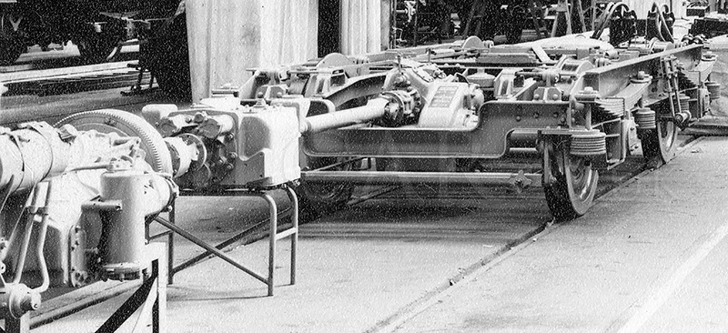
The image shows the early power train in a mock-up in Derby C&W Works in early 1955.
For later vehicles (79118-49, 79169-81, 79184-93 and 79900/1) the dynamo was moved from being engine mounted to the underframe and would be driven from the gearbox output shaft. The engine variant supplied without the dynamo was the A220Y. These vehicles now had Self Changing Gears R14 gearboxes and other detail changes with this equipment change was different dynamo control equipment in the control box and a different tacho display on the driver's desk (now round as on blue square vehicles rather than rectangular).
The exact equipment fitted to each batch can be determined from listings that appeared in BUT spare parts manuals. One vehicle was trialled with an automatic gear control system.
Each engine drove an exhauster which was used for the vacuum brakes, which used standard 18" coach brake cylinders mounted on the bogies.
They were not without their technical problems at first, perhaps that could be expected. Allegedly some of the problems arose because Derby C&W department refused to consult with their Locomotive department colleagues during the construction.
Bogies
BR's conventional bogie of the time was used, which was formed of mild steel, with the main frame members being riveted together and the individual members were partly fabricated. The bolsters were fitted with spring side control and side friction blocks. Roller bearing axleboxes were supplied by British Timken.
Control System
The control system for these units differed from the West Riding batch, so they would be designated as "yellow diamond" (same as the Met-Camm Lightweights) as opposed to "red triangle" which the West Ridings were.
Multiple working provision was made for four power cars.
Electrics
The 24v electrical system provided 60W lighting in the passenger saloons with standard coach fittings, early vehicles (at least the West Cumberland sets) had an LMS rectangular style, most vehicles had the familiar round bulls-eye (opaque white shades with silver rings) Smiths fittings. The drivers and guards lights were on different circuits. These and the control equipment were powered by batteries which were charged by dynamos, belt driven by either the engines or gearbox.
Heating
Underfloor mounted oil burning Smiths combustion heaters provided thermostatically controlled warm air through ducting the full length of the vehicles at floor level on both sides. The heater control switches were located in different places depending on the type of vehicle. Driving vehicles had the switches in the cab. TBS's had them in the guards compartment, and on other centre cars above one of the doorways. Instructions stated that the heater should be started 20 minutes before the advertised departure during the normal heating season, or 30 minutes before when the outside temperature was 35 degrees or less. During warm weather cold air could be supplied to the cars.
Interiors
Accomodation was originally in third class and first class, third would become second on June 3rd, 1956.
The floor was was covered with two thicknesses of flameproof hardboard and overlaid with linoleum.


The style of tubular steel framed seats differed between LMR and ER builds, the LMR vehicles having higher backed seats with a handle to the rear (first image), the ER seat had a lower back and curved at the top (second image).
The seats were trimmed with maroon moquette in third class and blue uncut in the first. The moquettes used also differed for each region. Vynide was used on head rolls and seat borders. First class saloons had a variety of seating arrangements (some even had reversible seats), second class normally in a 2+3 arrangement but some ER vehicles had a 2+2 arrangement.
Interior panelling was Vynide cloth covered flameproof hardboard, in various colour schemes. Luggage racks were provided along the complete length, formed from light alloy tubes of square section. All windows had pull down blinds.
There was a toilet in the composite vehicles, with the exception of the 4-car sets in which the two trailers had lavatories. The toilets had primrose plastic panels and rubber floor tiles.
Cab
The drivers cab was separated from the passenger accommodation by partitions with the top half in glass allowing passengers a forward/rear view. The drivers desk was only 1/3rd wide. The desk was formed of a metal frame and covered in black bakelite sheets with a metal protection strip over the centre area.
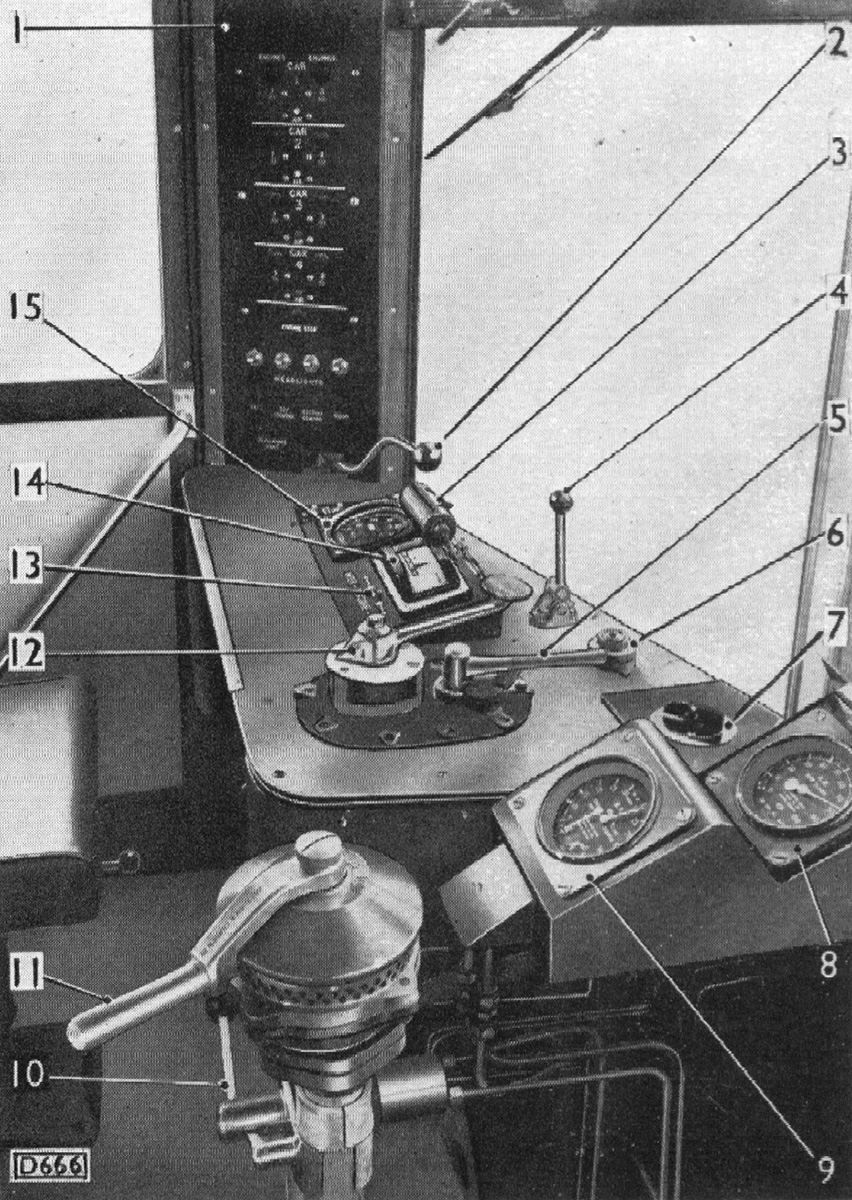
In the image of the drivers controls, from a BUT maintenance manual, the numbers correspond to:-
- Control panel
- Combined throttle lever and deadman's handle
- Control table light
- Horn switch
- Forward and reverse lever
- Windscreen wiper valve
- Headlight dimmer switch
- Air pressure gauge
- Duplex vacuum gauge
- Windscreen washer lever
- Handbrake lever*
- Change speed selector lever
- Engine speed indicator switch
- Engine speed indicator
- Speedometer
*As described in the manual, this is the vacuum brake handle for the normal train brake, on the right side of the cab was a wheel for the parking brake, also known as a handbrake.
On the drivers left, mounted at an angle between the windscreen and the door was the control panel, with start button for each engine, and one button which stopped them all together. There was a light for each engine, these were operated by an oil pressure switch fitted on the engine and told the driver whether an engine was on or off. There were controls for four cars, allowing four driver/trailer sets to be joined to form an eight car set. The control panel was formed from black bakelite with white lettering and fixed in place by a wooden strip either side.
Below the control panel were switches and indicator lights for the four headlamps, and then a light for the deadman’s. Below this there was the combined deadman’s/throttle control which swivelled at the base of the panel. If this handle was released for more than five seconds all engines returned to idling, the gearboxes returned to neutral (which prevented the engine from stalling) and the brakes were automatically applied.
In front of the driver was a small central raised section, angled towards the driver. On the left was the speedometer, and on the right the engine speed indicator. This type was belt driven, and had no actual speeds marked. It was rectangular shaped, with two positions marked to advise when to change up or down a gear. An arrow moved along the top edge in relation to the engine speed. A switch allowed selection of either the no.1 or no.2 engine to be displayed. Above the panel was a light to provide illumination for these gauges. To the right of this panel was the direction/gear selector. In front of the windscreen was the horn control, the windscreen wiper valve, and a switch for dimming the headlamps.
To the right of the desk on a stepped and angled display was the air pressure gauge and duplex vacuum gauge (items 8 and 9). On earlier vehicles (West Cumberland and Lincolnshire sets) these two gauges were fitted above the control panel (item 1), as they had been on the earlier West Riding sets.
At the secondmans side was the parking brake, standing on it’s own pillar. The wheel was fitted with a grab handle for fast application.
The drivers seat was adjustable for height and could also be swivelled. Behind the seat, on the lower back wall of the cab near the central door was the train switch (a mater electrical switch operated by a detachable lever). The central door into the passenger accommodation hinged in towards the cab, unlike most later DMUs which were sliding doors on runners. On the central cab windscreen was fitted a wooden box containing the destination blind. A cupboard below the secondmans windscreen contained the multiple working jumper cables when not in use.
Cab Fronts
West Cumberland cars had three full height windscreens. Very soon after delivery, after problems with windows cracking due to the vibration of the engines and general vibration on the West Riding sets, they had a strengthening bar fitted to the inside of the windscreen.
The remaining vehicles had each of the three windscreens divided into two giving even greater strength.
On the full height windscreens there was a single ordinary windscreen wiper, attached to the side of the window frame (drivers side). The split sceen vehicles, because of the divider, had a unique type of wiper centrally placed with two blades, one covering the upper pane of glass and one covering the lower pane of glass. As time went by, some vehicles were also fitted with a wiper on the secondmans side.
Marker lights had two white bulbs, never red, they had slots on the front which allowed a red lens to be inserted (carried inside the cab) but the use of these was soon abandoned and tail lamps were carried instead.
Automatic Gear Change
In mid-1956, a power/trailer LMR set was modified to take a VSC (variable speed control) unit which had been developed by Self-Changing Gears Ltd. of Coventry. The power car, 79135 kept its original engine and SCG R14 gearboxes and BUT final drives.
Instead of the normal five gear positions (neutral, first, second, third and fourth speeds), the new gear controller only had three, designated neutral, drive and hold. The gears were changed automatically through a specially designed control system, the heart of which consisted of a pair of electric generators driven from the transmissions. When starting off the driver had to move the gear control from neutral to drive and open the throttle. The gearboxes would change gear themselves in relation to the speed and gradient characteristics. The hold position would be used if the driver wished to remain in a particular gear, basically putting the VSC system out of use until the selector was returned to the drive position.
In practice, VSC omitted the characteristic “bump” felt when first speed was engaged, even with the throttle controller in the full open position. There was a marked delay between selecting drive, opening the throttle and the first forward movement, although this was a feature of the design. 79135 operated on the Blaenau Ffestiniog - Llandudno branch, so the “hold” position was well used, particularly on the troublesome ascent between Betws-y-Coed and Blaenau Ffestiniog, holding in second gear, to avoid it trying third and dropping back to second over and over again.
The drivers apparently liked the system once they got used to it, and it was thought the units would avoid abuse of the Wilson gearboxes and prevent abnormal wear. It also meant improved fuel consumption and a reduction in fluid coupling and transmission wear.
The VSC was an electrical method of selection and engagement of appropriate gear ratios, through the medium of magnet valves, as the speed of the vehicle changed. The speed at which gear changes occur could be suitably modified according to the position of the engine speed control. Generators that were driven from the gearbox output shaft produced a voltage signal which increased with the speed of the vehicle and operated relays in sequence. As each relay closed, it switched current to the next, thereby engaging a higher gear. When the speed (and generator voltage) fell, the relays were released in turn, and switched the current back to the preceding magnet valve, so changing down to the next lower gear (the system was an add on to the existing gearbox, meaning any standard cars could easily be altered). The relay panel for the VS automatic control was fitted into the cab, but could be fitted anywhere suitable on units, connecting to the vehicles wiring by multi-pin connectors.
This set was later fitted to Derby ‘Heavyweight’ 50049.