Blue Pullman
Brakes
The trains were fitted with a Westinghouse Electro-pnuematic brake featuring a high speed control and were operated by compressed air.
The essential features were:
An electrical driven air compressor was fitted on the underframe of each motor
car, and each compressor charged its own main air reservoir to a maximum pressure
of 125 lbs. p.s.i. These reservoirs were connected to each other by a common pipe,
called the main reservoir pipe, which extended the whole length of the train.
Connected to this pipe on each vehicle was a supplementary reservoir charged with
air at the same pressure. Another pipe extended the full length of the train called
the brake pipe and could be easily distinguished from the main reservoir pipe by
its slightly larger diameter. The brake pipe was connected to an auxiliary air
reservoir on each vehicle. Mounted on the underframe of each vehicle was an
electro-pnuematic brake unit connected to both the main reservoir pipe and the brake
pipe, this unit being perhaps the most important item of the brake system. Brake
cylinders with combined slack adjuster were mounted on the heavy type bogie frame of
the trailer bogies; these cylinders in turn were connected by fully compensated clasp
brake rigging to the brake blocks.

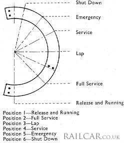
Control of the brake was established by means of a brake controller situated in each driving cab, the control handle had six operational positions as indicated in the diagram to the right.
Special features were incorporated into the Westinghouse air brake equipment to maintain the high efficiency at high speeds. Control was by electro-pneumatic valves and at train speeds at which normal braking was required the degree of standard brake pressure applied to the cylinders was proportional to the position of the driver's brake controller.
In the high speed range the brake pressure was automatically increased to compensate for the lower coefficient of friction of the cast-iron shoes when operating at high speeds. The changeover from high speed to normal speed braking, and vice-versa, was entirely automatic and was controlled by a valve energised by current from the speedometer generator. The de-luxe Pullmans were the first train to be fitted with two-stage EP braking.
Operating through switch contacts in the controller, the brake valve handle was also used to control the automatic brake for emergency use. The brake equipment incorporated the latest type of Westinghouse rubber-seated valves and O-ring packings for ease of maintenance.
Summary
Development
Press run 24/6/60
Press run 7/9/60
Staff difficulties
Ownership agreement
Manufacturer's Publicity
Description
Type 1 - LMR motor car
Type 2 - WR motor car
Type 3 - WR parlour 2nd car
Type 4 - LMR kitchen car
Type 5 - WR kitchen car
Type 6 - LMR/WR parlour 1st car
Interior
Air conditioning
Motor cars
Auxiliary power
Bogies & couplings
Brakes
Data
Sub contractors
Staff instructions
LMR services begin
LMR Publicity
LMR brochure
LMR handbills
Controversy
WR services begin
WR publicity
WR publicity brochure
WR publicity leaflet
LMR Operations
WR Operations
Liveries
Rundown & withdrawal
After service & preservation
Disposal
Maintenance Manuals
Miscellaneous
Acknowledgments & Further Reading
Images
No vehicles were preserved.


