Class 101 Met-Camm 2,3 & 4-car DMUs
Description

The body construction of these vehicles matched the earlier Met-Camm Lightweight vehicles, a steel body with aluminium roof panels. The roof construction can be seen in the image, from right to left - assembly, etch priming the alloy panels, and after applying red-oxide primer.
The vehicles that have been glossed and lined do not yet have doors or windows fitted.
The bogies were a Met-Camm design, not used by other manufacturers.
Technical Details
All vehicles were supplied with B.U.T. 150 h.p. engines. B.U.T. had two types of 150 h.p. engines - A.E.C. and Leyland, and the 101s were delivered with both types. For easier identification of the engine type an round identity holder was fitted to the vehicle solebar above the engines, although these fell out of use.
| Engines | A.E.C. 220 6-cyl 150hp* (Class 101) |
| Leyland 680 6-cyl 150hp (Class 102 - later reclassed 101) | |
| Transmission | Mechanical - S.C.G. R14 4-speed epicyclic gearbox with A.E.C. F239 axle mounted final drives on the inner axle of driving bogies. |
| Brakes | Vacuum, Gresham twin pipe quick release system |
| Bogies | DD15: DMBS, DMC |
| DT11: all trailers | |
| Wheelbase | Bogie 8' 6" spaced at 40' centres |
| Gangway Type | Midland scissor |
| Weight | DMBS & DMC 32 tons (approx) |
| All trailers 25.5 tons (approx) | |
| * from the late '70s the remaining AEC engined Class 101 power cars were equipped with Leyland engines of either the 680/1 or 680/1595 variants. | |

The image shows the Midland scissor gangway connection between a TSL and DMBS. Taken at Haymarket depot in 1984. S Saunders.
The vehicles power train equipment used all standard B.U.T. supplied items.
Technically they differed from the earlier 79xxx cars in their mutiple working equipment, cab controls and radiator header tank layout.
Brakes
Standard Gresham & Craven quick release vacuum brakes were used. Power cars had two 22 inch sliding band or 21 inch rolling ring vacuum cylinders, and two rotary exhausters — belt driven from the engines. Unpowered vehicles had two 18 inch vacuum cylinders.
This BR booklet has diagrams showing the brakework equipment layout and lists all the components with part and drawing numbers. Note it contained a second page 1 in the listing section, instead of a page 2.
Download PDF (14.2mb)
Wiring Schematics
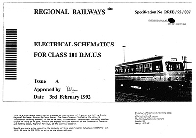
Dated February 1992. This is a 2mb PDF, courtesy of Chris Bull / DFR DMU Group.