Class 111 Met-Camm sets 2/3-car DMUs
LMR Power / Trailers
Consisting of four sets, M50134-7 (DMBS) with M56090-3 (DTCL)
Diagrams
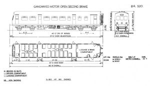
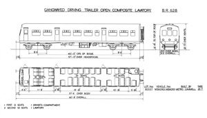
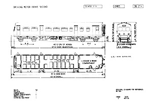
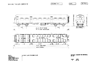
The diagrams for all three batches have clearly re-used a standard Class 101 tracing, the underframe layout is clearly wrong and shows the 150 hp engined variant. Overlaying the three DMBS images on top of one another it can be seen they are identical (including the text) apart from number and cab changes.
In addition the the van door arrangement is wrong for batches one and two as the later type is shown, the inward opening door would be on the left on both sides as you face the van doors from outside.
The DMBS was to BR Diagram 520 and the DTCL to BR Diagram 628.
Note the top lamps are missing from the cab views.
Design Codes
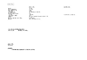
The DMBS was DQ 214 and the DTCL DS 312:
Works Photographs
Rolls Royce
Courtesy of Mike Jones. A letter that accompanied the images, mailed from one company employee to another in April 1957, notes: "...some of them you will you will probably chuck out as they are not really of very great interest. You will note that one some of the shots of the engine there are certain oil leaks showing and it might be better not to let anynoe see these photographs...".
These were probably taken at Met-Camm's Saltley works, and an almost completed 59051 in image WMP7810 dates them to around October 1956, when that vehicle was delivered. I've added my own notes on what they show.

Negative WMP7793
Through a floor hatch inside a vehicle. In the centre is the top of the compressor, the ribs to dissipate heat. To the bottom can be seen the short cardan shaft / universal joint to the radiator. The pipe with the wire wrapped around it will have holes drilled in it - this disperses the contents of the fire extinguisher over the engine, the wire wrapped around it is the pyrocord, this triggers the fire extinguishers when there is excess heat.

Negative WMP7794
In the adjacent hatch can be see the exhaust, the lighter ribbed pipe at
the bottom.

Negative WMP7795
The fluid flywheel end of the engine. The throttle motor is on the right of the oil splattered sump, the four air pipes control the four engine speeds.

Negative WMP7797
Just above the exhaust silencer is a heater, its air intake is on the right. The two cylinders are the engine air intakes / filters. Under the words 'Flame Switch', the two small cylindrical objects are fuel filters (a CAV type common on most DMUs). Under the builders plate are the engine start / stop buttons with a socket for an inspection light.

Negative WMP7798
The fuel pump can be seen mounted on the engine, the pipes from the top running to each of the six injectors. It is directly connected to the throttle motor, which has the four flexible air hoses running into it.

Negative WMP7802
Looking through a floor hatch to a final drive mounted on a bogie, the input shaft to the top. The white pipe is one of two air pipes to control forward / reverse, the ribbed pipe is a conduit for the wires which connect to the cab 'air/axle' lights to show the drive has engaged.

Negative WMP7810
Drivers controls, which appear identical to a Class 101. Note 59051 under construction on the adjacent road.

Negative WMP7811
Both engines can be seen in this underframe view, looking from the rear of the vehicle towards the cab end.
Metropolitan Cammell
The first three images were taken circa April 1957.
Summary
Description
- LMR 2-car
- NER 3-car (earlier)
- NER 3-car (later)
Refurbishment
Drivers Instructions & Adverts
Numbering
Liveries
LMR plans
Operations
Non-Passenger Use
Images
Details about the preserved Class 111 vehicle can be found here.


